DESCRIPTION
20509 Issue 7 Jan 2018 2-23
Pocket Terminal Connector (Data Entry 25-way
D Connector)
Data Input Pin Connections
For RS232 operation, pins 13 and 24 are linked to disable the 20mA loop.
Pins 4 and 9 may also be linked to set CTS. For 20mA loop operation, pins
21 and 22 are linked. The terminal as supplied has the connections set for
RS232 operation.
Data must be fed from the external source while the machine is being set
up or during non-print periods.
External Alarms
The printer has a set of changeover relay contacts which are operated at
the same time as the printer fault lamp. However, they are completely
separate from the printer circuits and are provided for external use. Wiring
to the contacts enters the cabinet through one of the cable glands and
goes to the motherboard.
The connections are:
• PL5/1 and PL5/2 (printer internal contacts normally open)
• PL5/1 and PL5/3 (printer internal contacts normally closed).
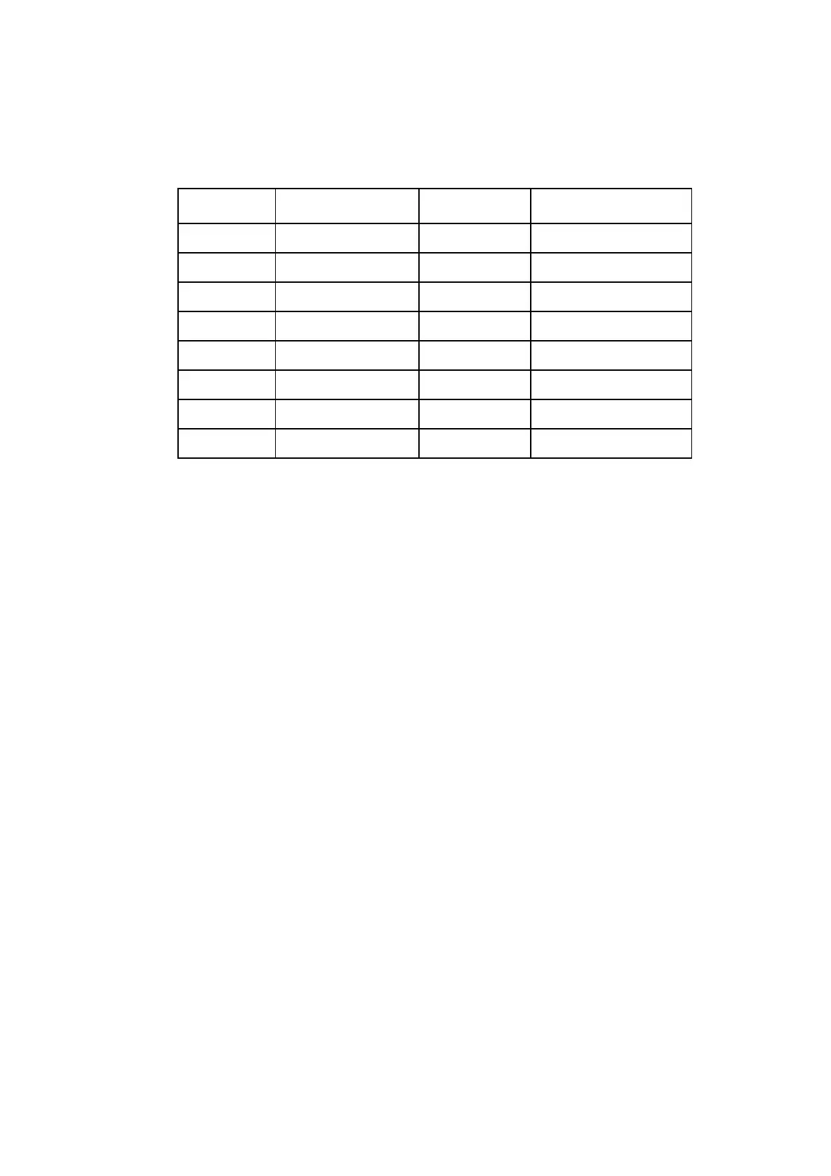
PIN SIGNAL PIN SIGNAL
1 0V 12 Tx +ve
2 RS232 Data In 13 Rx +ve
3 RS232 Data Out 18 -12V
4 CTS (Input) 21 20mA ENABLE
5 RTS (Output) 22 +12V
7 0V 24 Tx -ve
9 +5V 25 Rx -ve
11 20mA Source
 Loading...


