DESCRIPTION
2-8 20509 Issue 7 Jan 2018
The ink that emerges from the nozzle forms a drop, ejected onto the print
surface by the ink pressure. Drop size, density and quality of the print is
controlled by three factors:
• The time for which the solenoid is energized
• The position of the slug when the solenoid is de-energized
• The ink pressure.
Ink flow into the head can be shut off with the print head valve. A purge
switch operates all the nozzles to remove any air (see
page 3-4).
The print head is mounted at right angles to the print surface, at a distance
of 3 to 5mm for best print quality. At distances outside these limits, print
quality will be reduced.
Macrojet 2 has a number of print head and print options. The print options
are shown in the diagrams (see
page 2-9 and page 2-10). A 7 drop head
will print only the single line options. A 16 drop head is required to print the
twinline and large options. Up to four lines of print (7x5), by way of four 7
drop heads or two 16 drop heads, can be supplied from a single control
cabinet
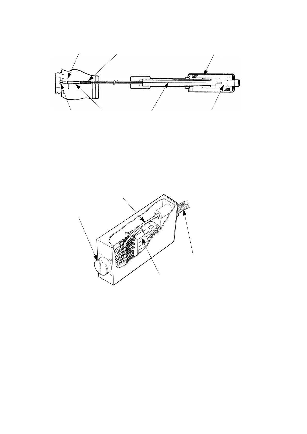
TP1291_1
Plunger Slug Slug Return Spring Solenoid
Nozzle Plunger Control Wire Solenoid Slug
TP1380_1
Nozzle Plate
Feed Pipe
Solenoids
Conduit
The Print Head
 Loading...


