23
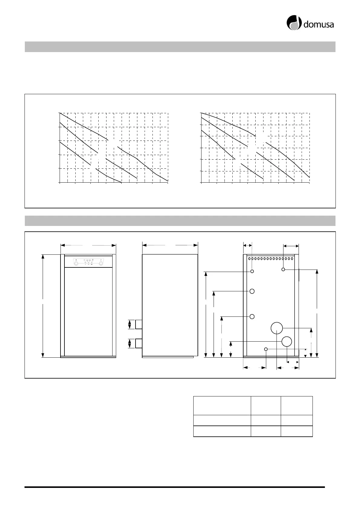
18 CIRCULATING PUMP FLOW CURVES
The hydrodriving pressure available in the installation at the boiler output can be deduced from the
following graphs, having taken the boiler pressure drop into account. The graph shows three curves,
which correspond to the three speeds of the circulating pumps supplied with the boiler.
NYL 43-15
0
1
2
3
4
5
00,511,522,533,5
Q(m
3
/h)
H(m)
III
II
I
NYL 53-15
0
1
2
3
4
5
6
00,511,522,533,5
Q(m
3
/h)
H(m)
III
II
I
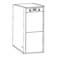
19 DIAGRAMS AND MEASUREMENTS
550
L
ø80
75
840
125
300
600
RC
IC
ø80
VS
680
260
65
EA
SH
SC
220
160
100
IC´
135
715
IC: Heating outlet.
IC': Optional heating flow.
RC: Heating return.
MODEL
IC, IC'
RC
L MEAS.
VS: Safety valve. EV 25 AC
1"M 855
SC: Condensation outlet, 3/4" H. EV 35 AC
1"M 955
SH: Fume exhaustion duct, Ø80.
EA: Air intake, Ø80.