31
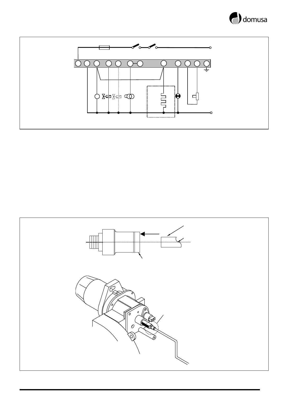
23.13 Electrical connection diagram
1 2 5 6 8
10 11 12
3
FR
TR
∼
MB
EV1
LB
RP
Black
Blue
TCTS
Ph
N
4
EV2
Preheater
F
7
B4: Time Counter Contact.
S3: Cut-off Light Contact.
TC: Boiler Thermostat.
TS: Safety Thermostat.
CH: Time Counter.
IG: Master Switch.
F: Fuse.
LB: Cut-off Light.
LB': External Cut-off Light.
FR: Photocell.
TR: Transformer.
MB: Motor Pump.
MB': Auxiliary Motor Pump.
EV: Valve.
RP: Preheater Element.
Ph: Phase.
N: Neutral.
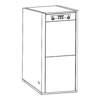
23.14 Quick connector
To connect and disconnect the red oil intake tube to the nozzle, proceed as follows:
- Press the connector ring in the direction of the arrow, pulling on the red tube at the same time.
PRESS
RING
TUBE
OIL
QUICK CONNECTOR