Evolution EV AC
24
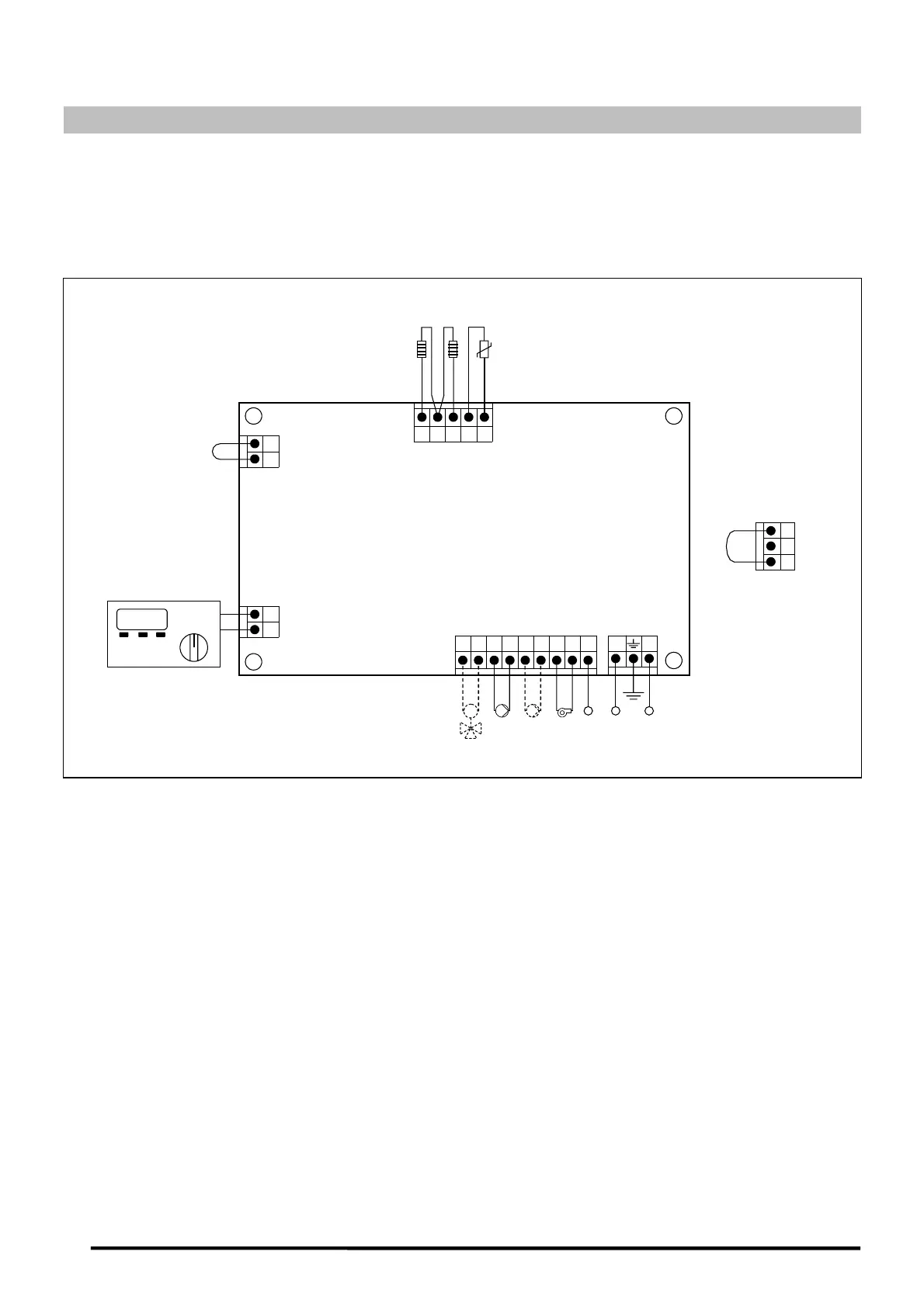
20 CONNECTION DIAGRAM
There are a series of removable terminal strips located on the rear of the control panel, for connecting
the various options and components for this model. For correct connection, carefully follow the
indications shown below:
1
356
7
89
10
11
4
J1J2
16
15141312
J3
J5
J4
N F
bc7
BC Q
Sc
TA
E20
Blue
Black
Blue
Azul
2
220 V
J6
1 2 3
RaRr
BV
Blue
M
Blue
BC: Heating pump.
BV: Hot water pump (storage heater option).
M: 3-way valve motor (option SRAC2/EV).
Q: Burner.
bc7: Burner terminal nº 7.
F: Phase.
N: Neutral.
Sc: Boiler sensor (on boiler).
Ra: Storage heater option resistor.
Rr: Underfloor heating option resistor.
TA: Room thermostat.
E20: E20 remote control.
J1: Supply connector.
J2: Component connector.
J3: Sensor connector.
J4: Remote control connector.
J5: Room thermostat connector.
J6: Telephone relay connector.