29
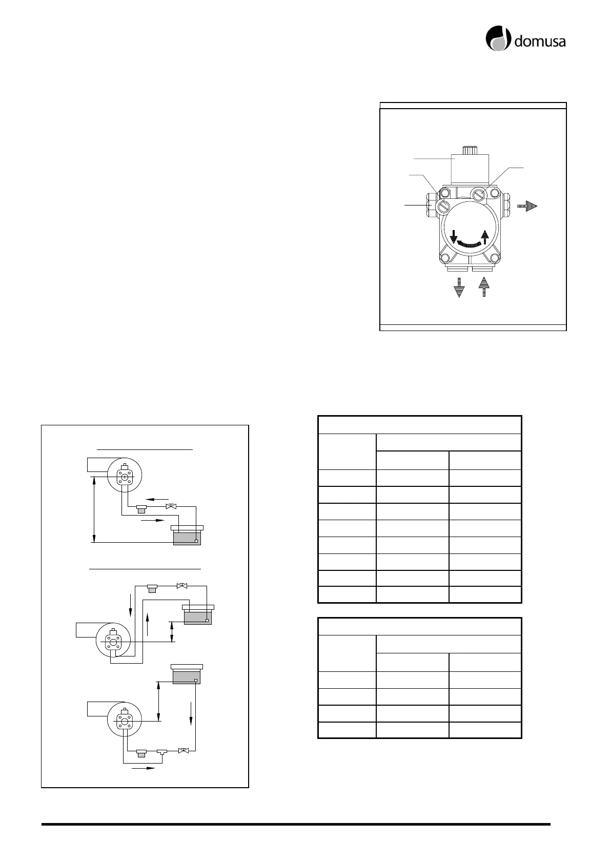
23.7 Oil pressure adjustment
To adjust the oil pump pressure, turn the screw
(1)
clockwise to increase the pressure, and
anticlockwise to decrease it.
1 - Pressure adjustment.
2 – Vacuum gauge point.
3 - Valve.
4 - Manometer point.
5 - Nozzle outlet.
6 - Return.
7 - Intake.
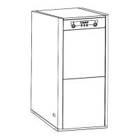
23.8 Oil supply piping diagrams
The diagrams and tables below correspond to installations without reductions and with a perfect
hydraulic seal. It is recommended to use copper pipes. A pressure drop of 0.4 bar (30 cmHg) must
not be exceeded.
Intake installation
H Pipe length
(m)
int.∅ 8 mm. int.∅ 10 mm.
0.0 25 60
0.5 21 50
1.0 18 44
1.5 15 38
2.0 12 26
2.5 10 26
3.0 8 20
3.5 6 16
Charging installation
H Pipe length
(m)
int.∅ 8 mm. int.∅ 10 mm.
0.5 10 20
1,0 20 40
1.5 40 80
2.0 60 100
WARNING: Check periodically the flexible pipes
conditions. Using kerosene, they have to be
replaced at least every 2 years.
MOD. AS47C
1
2
3
4
5
6
7
Intake installation
H
Charging installation
H
H