1835-065-N-1-21
11
14.6” 16”
12.8”
3.45”
14.7”
3.45”
Bottom ViewBottom View
Side View
Side View
Front View
Front View
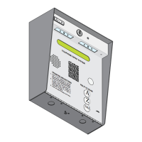
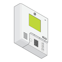
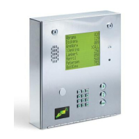
1.3.1 Flush Mount Kit Dimensions and Installation
The flush mount installation kit
has two parts; the rough-in box
and the trim ring. The rough-in
box is installed in the wall first.
Use appropriate hardware (not
included) to secure the box in the
wall. Run all necessary conduit
(not included) to rough-in box.
Slide the trim ring into the
rough-in box. Slide the enclosure
in the trim ring and secure them
all together with the hardware
included in the kit. Be sure the
unit is mounted securely and is
not subject to vibration from
closing doors or gates. See
previous page for flush mount
enclosure dimensions.
3.4”
3”
1.685”
1.74”
1.8”
3”
3.4”
6”
3.4” 3.4”
1.5”
1.74” 1.71”
Hole for Threaded Stud
Mounting
Hole
Threaded Stud
1.125” Dia
1.125” Dia
Rough-In Box Trim Ring
Flush Moun
t
Enclosure
Plastic Spacer
Locknut
Knock-outs
Rough-In
Box
Trim
Ring
Mounting
Holes
.25” Dia.
Mounting Screws
(Not supplied)
Mount In a Surface
Wall
7
8
9
4
5
6
1
2
3
0
OP
E
R
W
X
Y
Z
T
U
V
P
Q
R
S
M
N
O
J
K
L
G
H
I
DE
F
A
B
C
S
P
A
Z
C
A
LL
WARNING! If this entry
system is used to control a
vehicular gate with an
automatic gate operator, the
entry system must be
mounted a minimum of six
(6) feet away from the gate
and gate operator, or in
such a way that a person
cannot operate the entry
system and touch the gate
or gate operator at the same
time.