1835-065-N-1-21
21
NC
NO
RING
HF
1816
HS
ON
SPK
VOL
FEED
BACK
RS 232
ELEVATOR
MIC
VOL
OFF
KEYPAD
321
321
321
MASTER
CODE
16AC16ACBAT1NO1NC1C2RY2CAZIMC
5VDCIMDSPKRCOMMICPSWCGNDPHONE
1
2
3
12345 67891011121314
1
2
3
4
5
6
RS-232
19
20 - DATA - 1
21 - DATA - 0
22 - COMMON
23
24
25
26
27
28
29
30
31
32
33
34
35
36
Black
White
Green
16.5 VAC
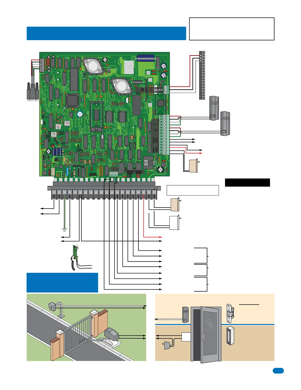
Power Input for Aux Terminal
14-Pin aux terminal.
Powers RS-232, elevator control and Wiegand inputs.
16.5 VAC
Red
Black (Neg)
Red (Pos)
Black (Neg)
Red (Pos)
Black
White
Green
Red
20 VA
20 VA
Power Input for 1837 Phone System
40 VA power for the 1837 phone system ONLY.
DO NOT use a 20 VA transformer for the 1837.
40 VA
Relay 0
Relay 2 Jumper
Auxiliary Terminal
Elevator Control Terminal
NO NC C
#7 thru #10 These terminals will
activate Relay 2 for its programmed
strike time.
#11 thru #14
These terminals will activate
Relay 1 for its programmed
strike time.
Power Input transformer for the phone system AND
Power Input transformer for the Aux Terminal must
be connected for the system to operate.
Relays activate a door lock
or a gate operator for their
programmed strike time at
a controlled access point.
Power wire
polarity does
not matter.
Power wire
polarity does
not matter.
Wiring MUST be twisted and
completely isolated from ground.
See section 2.1.4.
Power Transformers:
Use ONLY 16.5 VAC UL
Listed Transformer.
Run 18 AWG wire up to
100 Ft. Run 16 AWG wire
up to 200 Ft.
See section 2.1.1, 2.1.3
and 2.1.4 for further
information.
TONE ON
TONE OFF
Power Input for Phone System
20 VA power for the 1835 phone system ONLY.
DO NOT use a 40 VA transformer for the 1835.
Do Not Connect Power To A
Receptacle Controlled By A Switch.
ACT
2.3.1 ALL Telephone Entry Systems - NO Tracker Expansion Boards
2.3 Telephone Entry System Wiring
Basic Door Control ComponentsBasic Gate Control Components
“Optional” Elevator Control
Board Required for Elevator
Control
(Left terminal on elevator control board)
Power for relays on elevator control board is NOT provided
by the system. Use separate UL listed power supply.
See Elevator Control Board Manual 2348-065.
Wiegand Input (Relay 1)
26, 30 and 31-Bit Card Reader Input: Use 6 conductor,
stranded with overall shield. 18, 20, 22 or 24 gauge.
See section 2.1.2.
Wiegand Input (Relay 2)
26, 30 and 31-Bit Card Reader Input: Use 6 conductor,
stranded with overall shield. 18, 20, 22 or 24 gauge.
See section 2.1.2.
PC Connection See sections 2.4 and 2.5 for wiring RS-232.
Relay 1 Input
Telephone Entry Systems:
Control up to 3 entry points with ONLY the system circuit board.
Note: Separate elevator control board required for elevator control.
Note: When more than 3 entry points are needed to be controlled,
expansion boards will be required to accomplish this, see next 2 pages.
Main Terminal
Door Locks
Gate Operator
Power for electric strike or magnetic
lock is NOT provided by the system.
Use separate UL listed power supply.
Magnetic lock is wired to
the Normally Closed (NC)
relay input.
#5 & #6 - 16 VAC Output: Can be used to power lights on
card readers that have additional lighting for outdoor use.
“PSW” & “COM”
Switch Input -
See section 1.6 for Postal lock
connection.
A switch closure across these
terminals activates Relay 1 for its
programmed strike time.
See section 3.2.7 Switch Input
Feature.
“PHONE”
“PHONE”
Electric strike is wired
to Normally Open (NO)
relay input.
Gate Operator
is wired to
Normally Open
(NO) relay
input.
To #5 & #6 aux. terminal
for additional lighting on
card reader.
Lock Power
UL listed
Card Reader
Card
Reader
To a
Wiegand
Input Aux.
Terminal
To a Wiegand Input Aux. Terminal
To a Relay Input
To a
Relay Input
“1NO” - Normally Open (NO)
“1NC” - Normally Closed (NC)
“1C” - Common (C)
“2RY” - Contact (NO or NC)
“2C” - Common (C)
Relay 0 Input
NO - Normally Open
NC - Normally Closed
C - Common
Relay 2 Input
“2RY” Contact is set NO or NC with Relay 2 Jumper on board.
See section 4.6
Central Office
Phone Line Input
touch tone, loop start
Door
Lock
“CGND” Ground
See section 2.1.3.
500 ft max.
500 ft max.
UL 294
Tamper
Switch
(See Section 1.7).
Type of wiring to be used on ALL external devices:
A) Type CL2, CL2P, CL2R, or CL2X.
B) Other cable with equivalent or better electrical,
mechanical, and flammability ratings.
#3 & #4 - 12 VDC, .7 Ah, SLA Standby Battery Input
Standby battery power for Wiegand inputs ONLY. A separate standby battery is
needed for the phone system.
Battery must power system at least 30 minutes
to comply with Canadian certification (Battery not supplied).
“BAT” & “COM” - 12 VDC, .7 Ah, SLA Standby Battery Input
Standby battery power for the phone system ONLY. A separate standby battery is used for Wiegand devices
connected to the auxiliary terminal when standby battery power is being used. See aux terminal #3 & #4.
Battery must power system at least 30 minutes to comply with Canadian certification (Battery not supplied).