1835-065-N-1-21
14
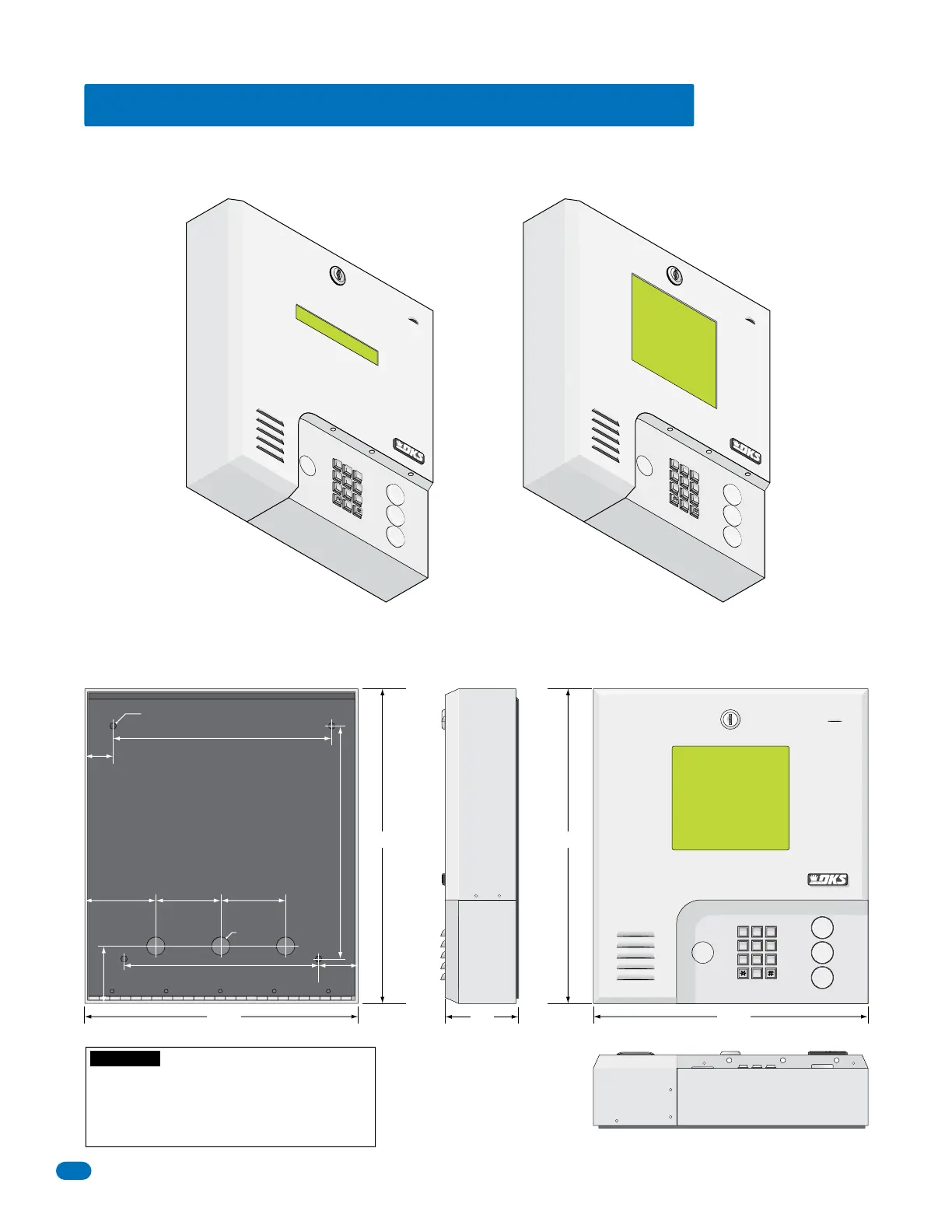
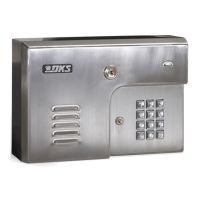
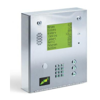
1.4 Wall Mount (Discontinued) Dimensions
Wall mount units (Discontinued) are designed to be mounted directly onto a wall without the need of cutting a large hole as is
necessary with flush mount units. Be sure the unit is mounted securely and is not subject to vibration from closing doors or
gates.
15”15”
13.25”13.25”
3.5”
Bottom View
Side ViewBack View Front View
7
8
9
4
5
6
1
2
3
0
OPER
WXYZ
TUV
PQRS
MNO
JKL
GHI
DEF
ABC
SP
CALL
Z
A
7
8
9
4
5
6
1
2
3
0
OPER
WX
YZ
TUV
PQR
S
MN
O
JK
L
GH
I
DE
F
AB
C
SP
A
Z
CALL
7
8
9
4
5
6
1
2
3
0
O
PE
R
WXYZ
TU
V
PQRS
MNO
JK
L
GHI
DE
F
AB
C
SP
A
Z
CALL
1835
1837
10.125”
1.5”
3.625” 3” 3”
10.875”
2.75”
9”
2.125”
25” Dia. Mounting Hole
.875” Dia
WARNING! If this entry system is used to control a
vehicular gate with an automatic gate operator, the entry
system must be mounted a minimum of six (6) feet away
from the gate and gate operator, or in such a way that a
person cannot operate the entry system and touch the
gate or gate operator at the same time.