1835-065-N-1-21
1
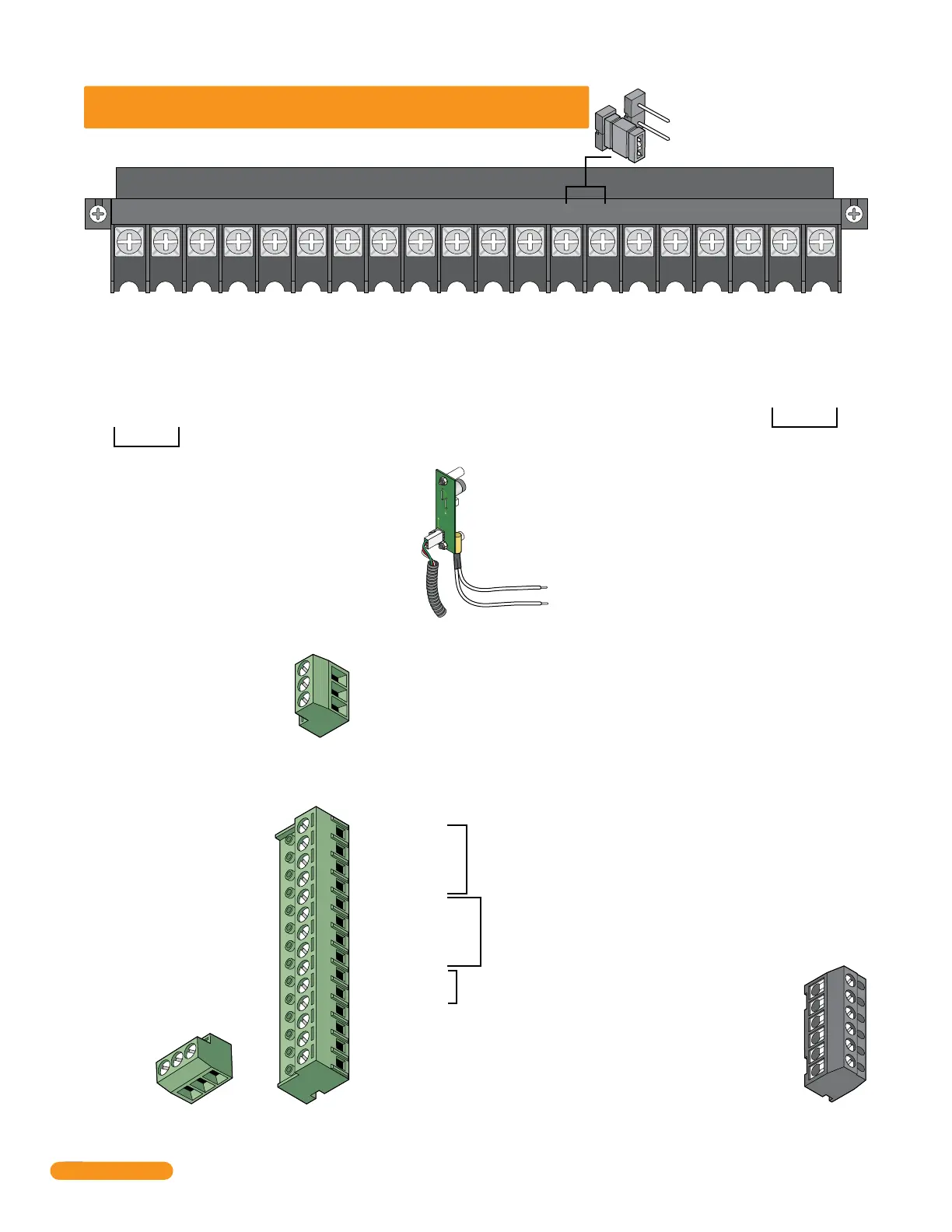
Phone Line Connection
16AC16ACBAT1NO1NC1C2RY2CAZIMC
5VDCIMDSPKRCOMMICPSWCGNDPHONE
1234567891011121314151617181920
Main Terminal
16 VAC Input Power
16 VAC Input Power
Standby Battery POSITIVE
For Phone System Only (12 VDC, .7 Ah, SLA) (connect negative to terminal 6)
Relay 1 Normally Open – 30 Volt, 3 Amp max.
Relay 1 Normally Closed – 30 Volt, 3 Amp max.
Relay 1 Common – 30 Volt, 3 Amp max.
Relay 2 Contact – 30 Volt, 3 Amp max.
Relay 2 Common – 30 Volt, 3 Amp max.
“A” Button Input.
“Z” Button Input.
14 +12 VDC Power.
13 Common.
12 DATA 1.
11 DATA 0.
10 +12 VDC Power.
9 Common.
8 DATA 1.
7 DATA 0.
6 16 VAC Output.
5 16 VAC Output.
4 Standby Battery NEGATIVE (For Wiegand Only).
3 Standby Battery POSITIVE (12 VDC, .7 Ah, SLA).
2 16.5 VAC Input Power – 20 VA.
1 16.5 VAC Input Power – 20 VA.
(Powers RS-232, elevator control and Wiegand)
1 DATA 1 – Connect to terminal 20 of elevator control board.
2 DATA 0 – Connect to terminal 21 of elevator control board.
3 COMMON – Connect to terminal 22 of elevator control board.
Transmit Data 1
Receive Data 2
Request to Send 3
Clear to Send 4
Signal Ground - Shell 5
Not used 6
(Not used).
5 VDC Power for LED lighting.
(Not used).
Speaker Output.
Common for switch input #4, microphone,
speaker, AZ & CALL buttons and battery neg.
Microphone Input.
Switch Input. A closure between terminals 4 and 6 will cause the designated relay(s) to activate for
the programmed strike time or dial a phone number – see 3.2.7. The Postal Switch is connected here.
Earth Ground Only (See Section 2.1.3).
Phone Line Connection
1
2
3
14
12
13
11
10
9
8
7
6
5
4
3
2
1
Aux Terminal
Removable
RS-232
Terminal
Removable
Elevator Control
Terminal
Non-Removable
Relay 0 Terminal
Non-Removable
Note: Connect to the Elevator Control Board (2348-010).
See Elevator Control Board Manual 2348-065 for more info.
100 ft. max. with 18 AWG wire.
200 ft. max. with 16 AWG wire.
20 VA min. for 1833, 1834 and 1835, 40 VA min. for 1837.
800 ft. max. with 24 AWG wire.
1600 ft. max. with 22 AWG wire.
(Wiring MUST be twisted and completely isolated from the ground)
Note: The 14-pin aux terminal can be removed for easy
wiring. Expansion boards are connected here when used.
See Expansion
Tracker Board
Manual
2358-065 and
section 2.3.2,
2.3.3 for more
information.
Note: Located in the upper left corner of circuit
board. The 6-pin terminal can be removed for
easy wiring. Connects a PC (See Section 2.5.1).
Relay 2 Note: Normally Open and
Normally Closed relay jumper is
used to set Relay 2 input on the
circuit board (See section 4.6).
NO
NC
C
Normally Open – 30 Volt, 3 Amp max.
Normally Closed – 30 Volt, 3 Amp max.
Common – 30 Volt, 3 Amp max.
1
2
3
4
5
6
NC
NO
26, 30 and 31 Bit
Wiegand input (Card Reader)
activates Relay 1 for
programmed strike time
26, 30 and 31 Bit
Wiegand input (Card Reader)
activates Relay 2 for
programmed strike time
For card readers that have additional
lighting for outdoor use.
QUICK GUIDE: Terminal Descriptions
See section 2.3 for terminal wiring.
UL 294
Tamper
Switch
Note: Located under microphone
board (See Section 1.7).
Quick Guide - 1