DORMA AUTOMATICES, Inc. 924 Sherwood Drive Toll-Free: 877-367-6211 Subject to change without notice
DL3463-050 08/2016 Lake Bluff, IL 60044 Fax: 847-249-3999
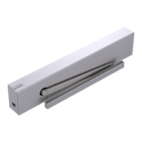
ED100 / ED250 SERVICE MANUAL
—
29
Parameter detail
Parameters / Display Value range
Unit
factory setting
= bold
Explanation
28. Control unit 24 VDC
output X3-1g, with
input 4/4a
0 – 1 0 Locking device output terminal 1G is independent of contact 4/4a.
1
■ Locking device output (terminal 1G) is turned ON as soon as
contact 4/4a is opened (v1.9).
■ Terminal 1G is on permanently (as long as contact 4/4a is open), so
it requires an electric opener with 100% duty factor.
■ This function is not active for motor locks via DCW.
29. Cycle counter
0 – 99 10,000
cycles
■ Number of cycles is displayed is shown in increments of
10,000 cycles, for example:
Display shows 4 = 40,000 cycles,
Display shows 53 = 530,000 cycles.
■ Value can be precisely displayed with DORMA hand-held
terminal.
■ A value of 99 on internal display means 990,000 or more.
30. Delete error log
0 – 1 0 No function.
1 ■ Error log is deleted.
■ Parameter is then automatically reset to 0.
31. Reset service
interval display
(yellow LED)
0 – 1 0 No function.
1 ■ Service cycle counter and time counter are reset to 200,000
cycles and 12 months (v1.7).
■ Any values other than this must be made with the DORMA
hand-held terminal (also see service LED function).
32. Factory setting level
1 – 2 1 ■ The SL parameter is used to determine what data will be
deleted during Factory settings process.
■ Standard Factory settings: pressing Fact Setup button on user
interface (Section 7) for > 8 seconds:
Resets operator to standard (original) factory settings.
Installed upgrade cards remain valid and do not require
reinstallation.
2 Extended factory settings; pressing Fact Setup button on user
interface (Section 8) for > 8 seconds:
Resets operator to standard (original) factory settings.
Installed upgrade cards are deleted from operator memory.
Parameter is automatically reset to 1.
Control unit and upgrade card can be usedindependently of
one another again (delivery status).
33. Opening angle
0 – 110 Degrees ■ Opening angle set during learning cycle is displayed.
■ Opening angle can only be changed during learning cycle.
■ Due to installation and parameter tolerances, display may not
match actual door position.
34. Door closer mode
0 – 1 0 ■ Automatic mode. This door closer mode is especially suitable
whenever door is mainly opened automatically and where
motion detectors are installed.
■ Optimized for high frequency use.
■ Full energy card provides for higher door opening and closing
speeds.
■ In case door is blocked during a closing cycle, operator reverses
automatically.
■ Door's driving phase is optimized to insure reliable closing cycles.
■ Keep-closed force (FH) and Push & Go function (PG) parameters
are only available in automatic mode.
1 ■ Manual mode. This door closer mode is especially suitable
whenever door is mainly used manually and only rarely
automatically.
■ In case door is blocked during a closing cycle, it will stop at its
current position.
■ Door's driving phase is optimized for manual opening cycles.
■ Power Assist Function (hf) parameter is only available in door
closer manual mode.