DORM
ED400 In Floor
Controller Manual
23
DORMA AUTOMATICS, Inc. 924 Sherwood Drive Toll-Free: 877-367-6211 DL3128-010
Lake Bluff, IL 60044 Fax: 877-423-7999 10/1/2007
E-mail: automatics@dorma-usa.com Subject to change without notice
APPENDIX
WIRING
Encoder / Cam Switch wiring
Encoder only
the 4 wires from the encoder should already be connected properly to the 5-position connector. If you need
to wire it, here is how.
The 2 middle wires (Phase A and B, Yellow and Green) can be swapped without a problem: the software
is smart enough to figure which way the motor is turning, and it interprets the 2 phases correctly.
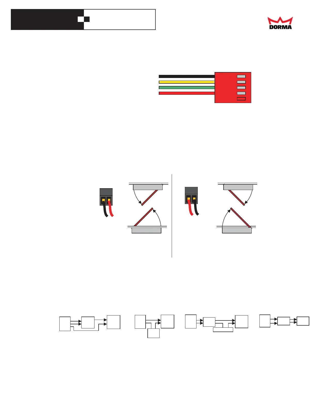
Motor wiring
From the factory, the motor wires are already connected properly to their 2-screw terminal block. If you
need to rewire it, here is how.
The red and black wires go to the other 2 screws, depending on the opening direction of the door. For
CW opening (as seen from above – that's a right hand door), the back wire goes to the screw closest to
the side of the box. For CCW opening (that's a left hand door), the red wire goes to the screw closest to
the side of the box. The black wire goes to the opposite screw.
AC Power wiring
The green wire goes to the middle screw. When looking at wire openings, with the screws towards up, the
line wire (usually black) goes the left hole, and the neutral (usually white) goes to the right one.
ELECTRIC LOCK
The controller may power an electric lock through a relay or access control device.
• If the installation has a 24 Vdc electric strike plate (a.k.a. electric lock), the controller
is able to power it directly. For DC lock of other voltages, you will need a separate power supply.
For AC locks, you will need a separate transformer and a relay.
• Don't forget to set the Open Delay to delay the door opening until after the lock has had a chance to open.
• The controller drives the electric lock from when it receives a valid trigger (at Latch-Stop), while waiting to
open (because of a non-zero Open Delay, or because the swing area is occupied) and until some time after the
door has begun to open. It also drives it ifthe door reaches Latch-Stop as it is retriggered. The LOCK LED
lights up while the controller drives an electric lock, whether or nor a lock is actually present.
GROUND BLACK
PHASE B YELLOW
PHASE A GREEN
+5 VRED
For a CCW opening door
(as seen from above)
For a CW opening door
(as seen from above)
BLACK
RED
Left Hand Rear
Right Hand
RED
Right Hand Rear
Left Hand
BLACK
12 Vdc
Electric
lock
12 Vdc
Supply
+-
+24V
LOCK
COM
Controller
+24V
LOCK
COM
Controller
24 Vdc
Relay
24 Vdc
Electric
lock
Access
Control
Controller
+24V
LOCK
COM
Electric
lock
Vac
Electric
lock
Transformer
24 Vdc
Relay
+24V
LOCK
COM
Controller