DORM
ED400 In Floor
Controller Manual
4
DORMA AUTOMATICS, Inc. 924 Sherwood Drive Toll-Free: 877-367-6211 DL3128-010
Lake Bluff, IL 60044 Fax: 877-423-7999 10/1/2007
E-mail: automatics@dorma-usa.com Subject to change without notice
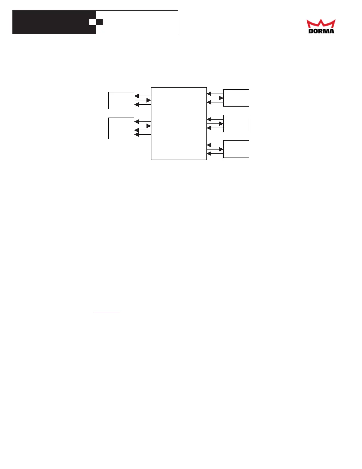
Motion
Sensor
Header
Presence
+24V
TRIGGER
+24V
HEADER
DATA
COM
+24V
SWING
+24V
APPR.
+24V
BEAM
Swing
Presence
Approach
Presence
Safety
Beam
CONTROLLER
Sensors
• Get power for any sensors that require it from any of the screws in the "+24" terminal block,
and any of the screws in the "GND" terminal block. These are the 2, 8-screw, blue terminal
blocks on the right end of the front panel.
• The trigger device (motion sensor (radar) or other device) goes to the "TRIG" terminal.
Connect its common to the Ground terminal, and, if required, connect its power to the +24 V
terminal.
• The header (jamb) mounted presence sensorgoes to the "HEADER" terminal. Connect its
common to the Ground terminal, and its power to the +24 V terminal. A dual zone sensor
(such as the BEA DK-12) needs a "DATA" signal: connect it to the "DATA" terminal.
• The door-mounted, approach side presence sensor goes to the "APPR" terminal. Connect its
common to the Ground terminal, and its power to the +24 V terminal.
• The door-mounted, swing side presence sensor goes to the "SWING" terminal. Connect its
common to the Ground terminal, and its power to the +24 V terminal.
• If the installation has a safety beam, connect it to the "BEAM" terminal. Connect its
common to the Ground terminal, and its power to the +24 V terminal.
Electric lock
The controller may power an electric strike plate (a.k.a. electric lock), through a relay or access
control device. The appendix has more information.
Program Switch
• This is the On/Auto/Hold-Open switch
• Install the switch by the door
• Route its cable to the controller
• Cut off excess cable, strip the 3 wires
• Connect the 3 wires to the removable, 3-screw terminal block in the lower right corner of the
controller's front panel. (Note that when you press one end of a rocker switch, it connects the
middle terminal to the one on the oppositeend; this could be counterintuitive.)
o The common wire (black) goes to the middle screw.
o The lower wire when the switch is mounted (white) goes to the upper screw
(this is the Hold-Open wire).
o The upper wire (red) goes to the lower screw (this is the Off wire).