15
ED50/ED100/ED250 09-2021DL4617-003
dormakaba ED50/ED100/ED250 OHC Header
Setup and Troubleshooting Instructions
Chapter 8
Terminal board connections
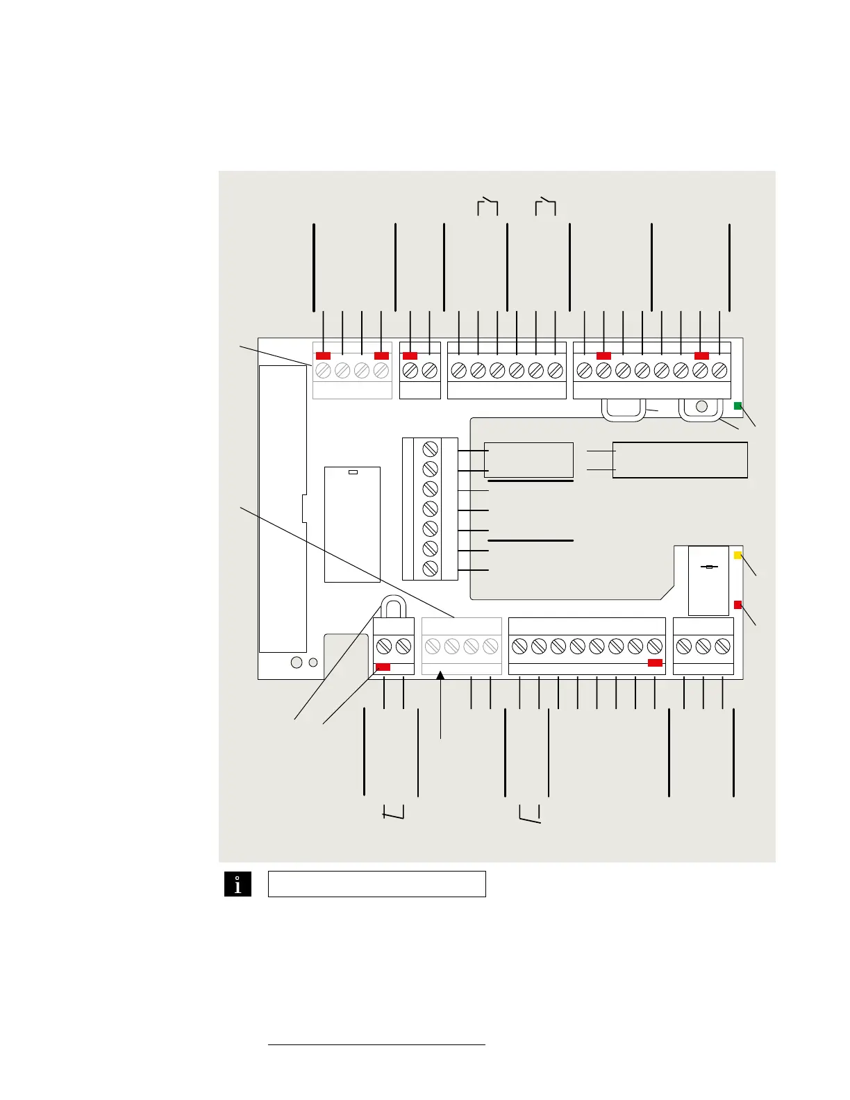
Fig. 8.1.1 ED50/ED100/ED250 terminal board electrical connections
1 Green LED (Para. 4.4)
2 Yellow LED (Para. 4.4)
3 Red LED (Para. 4.4)
4 Key (red insert)
location in socket.
Assigned plug has
tab in same location
broken off.
5 Jumpers, factory
installed at following
terminals:
• and a
• and *
• and *
6 DCW upgrade card
plug
7 Fire protection
upgrade card plug
TIPS AND RECOMMENDATIONS
• Use documentation provided
with each device for electrical
installation.
• It is recommended not to
connect system accessories to
board until after operator has
been setup and learning cycle
performed (Chapter ).
97 98 99 30 31 32 34 33 3335
1
36
1
4
4a
3
BA
1
57 57a
142
3
141
3
1
15
17
3
111
13 3
43 3646362
1G
3
+ 24 V
Signal input
0 V
Partial Open
Permanent Open
Exit Only
Automatic
Off
N.C.
COM
Test output
X5X4
X3
X6 X9 X1 X7
+ 24 V
X8
0 V
X10
8 - 24 AC/DC
+ 5% Wet
DCW bus
Safety sensors
Interior Exterior
Night-
bank
input
+ 24 V
Signal input
0 V
+ 24 V
+ 24 V
Signal input
Signal input
0 V
0 V
Test output
0 V
24 V
Brake coil
signal
Output
COM
N.O.
N.C.
0 V
Locking relay
Maximum current:
1A, 48 V DC/AC
Locking feedback contact
0 V
0 V
+ 24 V
0 V
0 V
Signal input
N.O.
Smoke
detectors
Emergency
close
Night
trigger
Mode, Exit Only
switches
Door status
24 VDC
Class II
1
2
3
4
5
6
7
5
5
ED50 ED100/ED250
0 V
Maximum current
load: 1.5A
24 V
Swing side Approach side
Note : ED/ED: Terminals and
are also used for swing side overhead sensor
input when parameter ST is set to or .
Reference Appendix A, Parameters.