64
ED50/ED100/ED250 09-2021DL4617-003
dormakaba ED50/ED100/ED250 OHC Header
Setup and Troubleshooting Instructions
Appendix B
B. Information and error codes
Appendix B - Troubleshooting
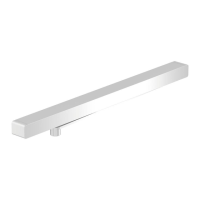
1 4 button keypad
2 2 digit display
Fig. B.1.1 User interface
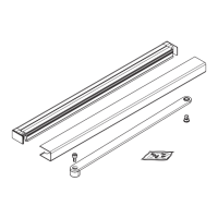
3 Power switch
4 Red LED
5 Yellow LED
6 Green LED
Fig. B.1.2 Operator LEDs
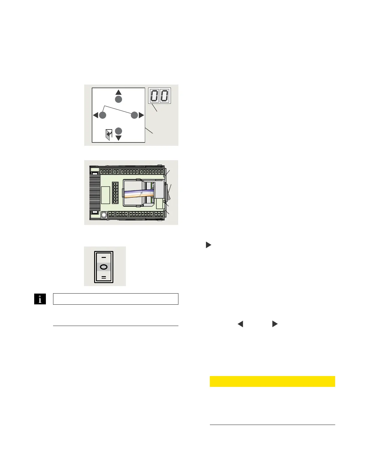
Fig. B.1.3 Mode
switch
7 Mode switch,
Close position
B.. Overview
Operator monitors internal circuits and external safety
circuits managed by the operator.
B.. Error and information messages.
. With operator in use, certain conditions may develop
resulting in error or information messages.
. Operator attempts to identify the cause and respond
accordingly.
. Response depends on the severity of the error:
• Information message (ln)
• Error message (E)
• Deactivating the operator's automatic function;
operator will switch to emergency mode. Users can
then access door manually.
B.. User information display.
User interface display, or or dormakaba handheld
displays:
• Information ln codes
• Error message E codes
B.. Viewing error messages.
To access and view error messages, briefly press the
right
button on the button keypad.
B.. Red LED on operator .
Red LED adjacent to operator power switch displays
blinking codes for:
• Certain ln information
• E error codes (Para. B.)
B.. Resetting error codes.
Options for resetting error codes:
. Set Mode switch in Close (off) position.
. User interface Reset buttons:
• Press both left
and right buttons >s to reset
system (v.).
• Header cover must be opened to access user
interface.
. Power reset:
• Turn power switch OFF.
• Turn power switch back on after seconds.
CAUTION
Always analyze and remove cause for error
before resetting error message!
Troubleshooting charts (Para. B.,.) are
intended as a guide for diagnosing errors.
TIPS AND RECOMMENDATIONS
Para. B.3, Information codes
Para. B.4, Error codes
> 3s Reset
< 3s Quit
> 3s
PRG
< 3s
LEARN
Fact-Setup
> 3s
> 8s
1
2
4
5
6
3