25
ED50/ED100/ED250 09-2021DL4617-003
dormakaba ED50/ED100/ED250 OHC Header
Setup and Troubleshooting Instructions
Chapter 11
1
2
. Set braking circuit plug position
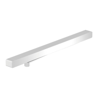
Fig. 11.2.1 ED operator control board
1 Braking circuit plug
2 Braking circuit
3 pin socket
3 User interface
5 Power fail closing
speed
potentiometer
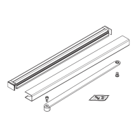
Fig. 11.2.2 Plug position, outswing
Fig. 11.2.3 Plug position, inswing
1 Braking circuit plug
2 Braking circuit
3 pin socket
5 Power fail closing
speed
potentiometer
1 Braking circuit plug
2 Braking circuit
3 pin socket
5 Power fail closing
speed
potentiometer
.. Set braking circuit plug position.
• Operator braking circuit plug is
positioned in its pin socket for an
outswing or inswing installation.
WARNING
Braking circuit will not work correctly
if braking circuit plug is improperly
positioned, or if an incorrect plug is
used!
Door may close at high speed
and/or be difficult to open!
.. Braking circuit plug outswing
position.
• Braking circuit plug is factory installed in
the two pins away from user interface,
the outswing position (Fig. ..).
.. Changing braking circuit plug
position to inswing position.
. To change plug position to inswing
installation, install plug in right two pins,
toward user interface (Fig. ..).
WARNING
Power switch (Fig. 11.2.4) must be
OFF before changing plug position!
1
2
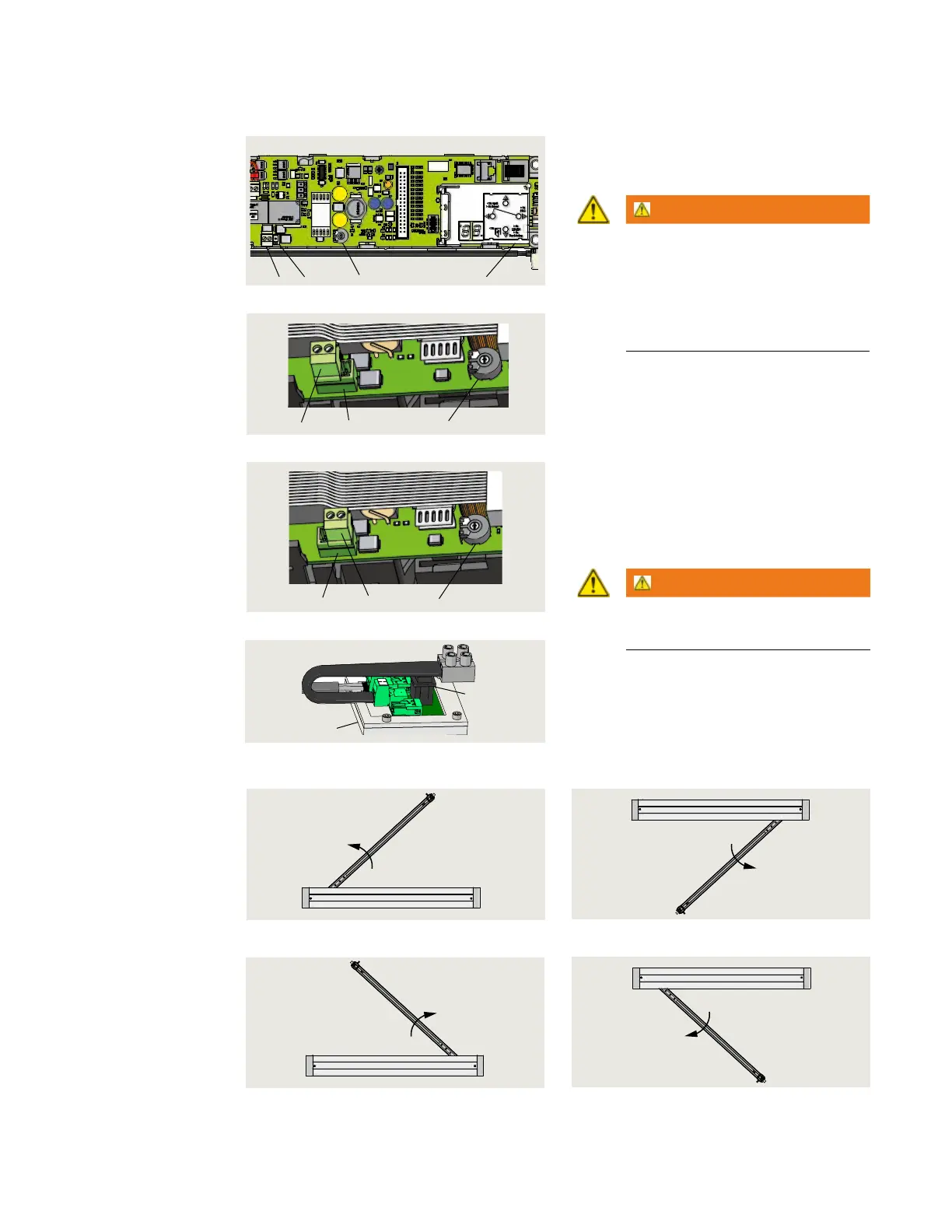
Fig. 11.2.5 LH outswing
Fig. 11.2.6 RH outswing
Header cover
Fig. 11.2.7 LH inswing
Header cover
Fig. 11.2.8 RH inswing
.. Door configurations.
3 Power switch
4 115 Vac module
Fig. 11.2.4 115 Vac power switch
3
21 3
5