Functions (water) - 14
Version 1.36
02/2004
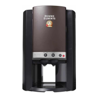
6. Disconnect the connector (4 wires) of CN11 in the upper right corner of the control PCB and
connect instead the prepared connector (2 wires).
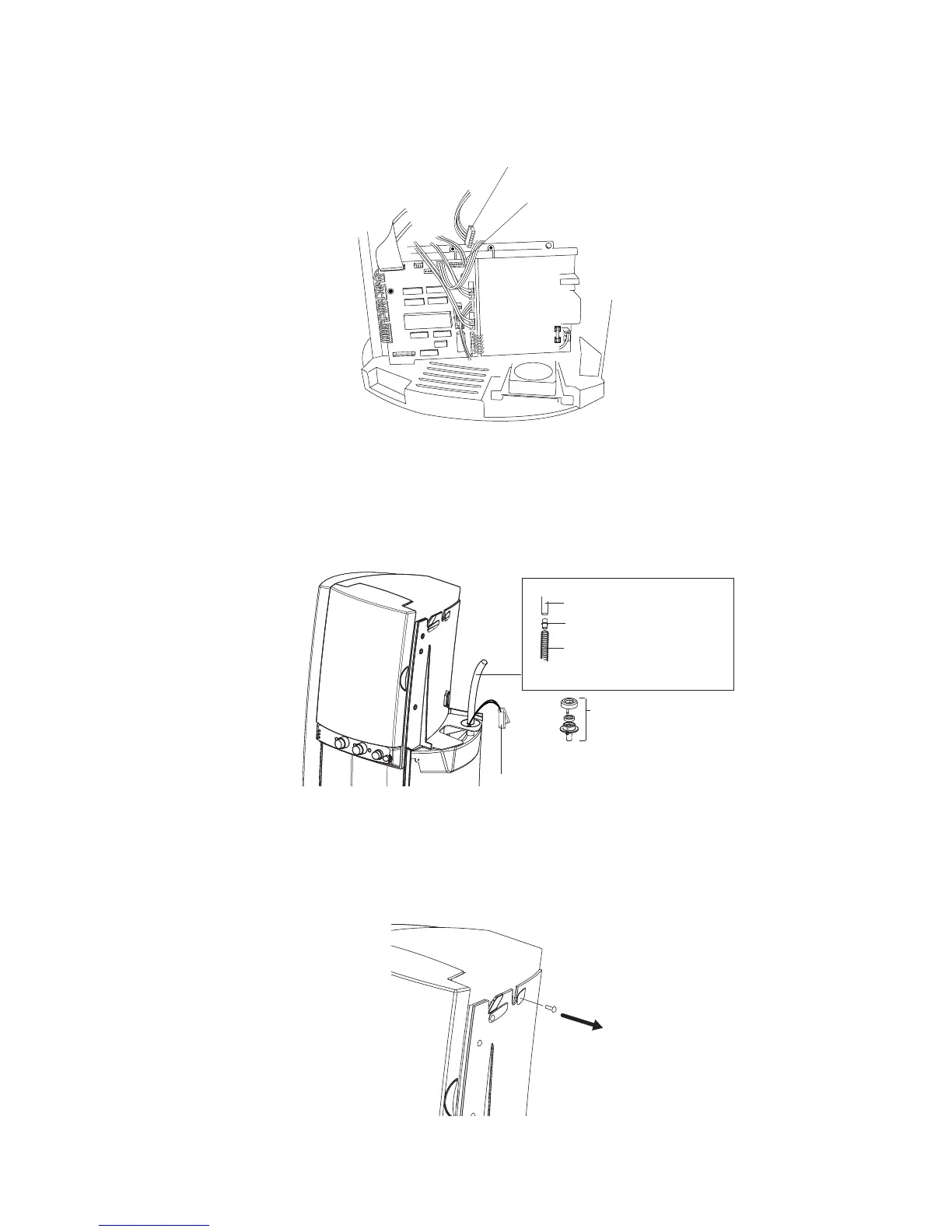
7 Disconnect the silicon hose of the water inlet assembly and remove the water inlet assembly itself.
8. Connect the hose included in the kit and connect it directly to the water supply hose.
Guide the hose together with the wiring through the opening in which the water inlet assembly
was installed. Reinstall the right cover (electronics cover).
Disconnect current connector (4 wires)
Connect new connector (2 wires) at CN11
New wiring for the inlet
valve coming from CN11
Removed : Water inlet
assembly
Hose connector
Silicon hose included in kit
Existing silicon water supply
hose
9. Remove the retaining screw from the machine frame as illustrated and place the water tank
with the pre-installed valve. Guide the hose and wiring through the opening in the bottom of the
tank.