16
6 Electrical Connection
IPack C3.3 can work in single mode and parallel mode. To make the battery work properly, follow the
instructions below to correctly connect it.
This chapter describes how to make cable and wires, and connect one battery and multiple batteries. If you
have finished-cable and wires already, skip Section 6.1 and 6.2. Otherwise, read 6.1 and 6.2 carefully.
6.1 Power Terminals and Network Ports
The battery provides the following
three network ports and two power terminals for electrical connection.
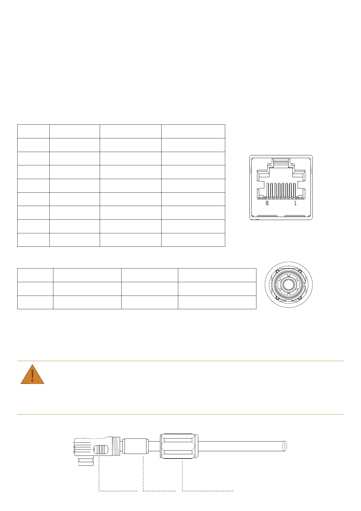
Table 6-1 Pin definition of network ports
Pin No. PCS Link-In Link-Out
1 RS485_B CAN2_H CAN2_H
2 RS485_A CAN2_L CAN2_L
3 NA Ecode_IN+ Ecode_OUT+
4 CAN0_H ISO_GND ISO_GND
5 CAN0_L Master IN Slave IN
6 NA Dry1- Dry1-
7 PCS_WAKE- Dry1+ Dry1+
8 PCS_WAKE+ Syn_Wake In/Out Syn_Wake In/Out
Table 6-2 Power terminals
Terminal Description Specifications Cable Cross-section
+ Positive terminal 1 Max. 120A 25 mm
2
- Negative terminal 1 Max. 120A 25 mm
2
6.2 Prepare Cables
Before connecting the batteries, prepare cables that meet the requirements of your applications.
CAUTION
Unqualified power wires might result in damages to the battery and your power system.
If you make cables on your own, please ensure that the terminals are crimped properly.
Step 1.Make power wires.
Joint Sleeve
Sealing
Sealing Nut