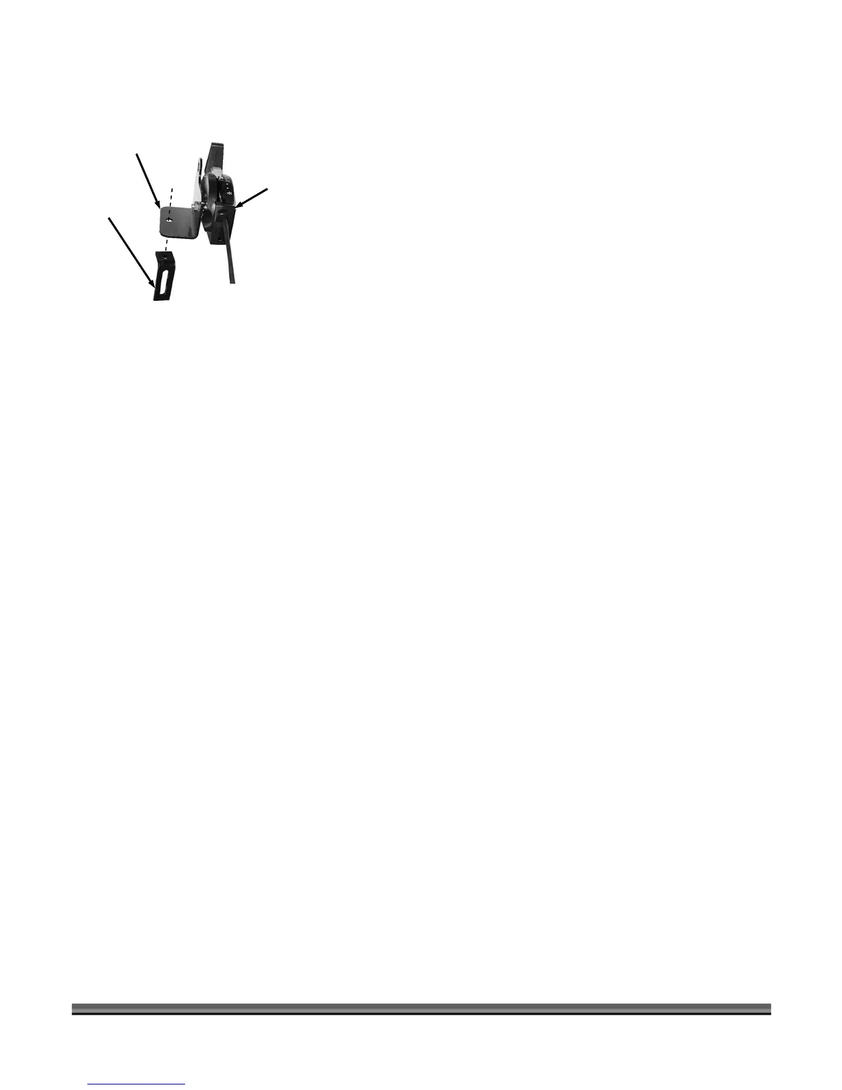
Mounting the Flow Control Lever Assembly
Mounting
Clamp
Bracket
Flow Control
Lever
Assembly
1. Find a place on your tow vehicle to mount the Flow
Control Lever Assembly where you can operate while
sitting on the vehicle. If there is not a hole in the area
to mount a 5/16” bolt then you must create one.
2. Using a 5/16" x 1-3/4" Carriage Bolt and Wing Knob
from the Hardware Package, mount the Flow Control
Lever Assembly to your Tow Vehicle (Figure 15).
3. If a different mounting position is required, use the
Mounting Clamp from your Hardware Package to
change the position of the Flow Control Lever
Assembly. You will need to provide the hardware to
mount the Mounting Clamp to the tow vehicle.
Figure 15
12 DR
®
ROTO-HOG™ POWER TILLER - OPTIONAL ACCESSORIES