Installing the DR POWER SPREADER
Tools Needed:
• 7/16" Wrench and Socket
• 1/2" Wrench and Socket
Instructions:
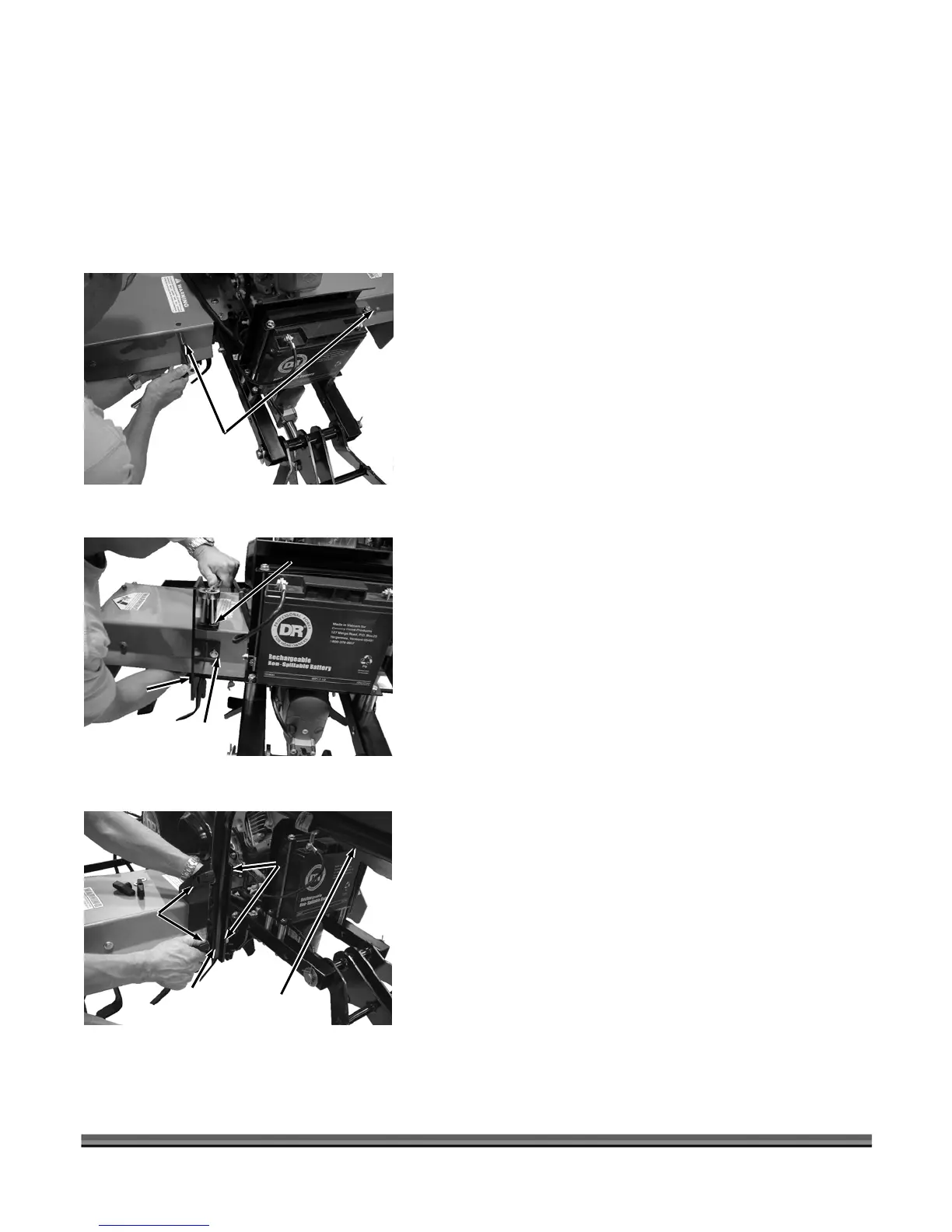
1. Remove two 5/16-18 X 2-1/4" Hex Head Bolts,
Washers and Nylock Nuts (1/2" Wrench) from the
back face of the ROTO-HOG POWER TILLER Fender
(Figure 3).
Tiller Fender
Hex Head Bolts,
Washers and
Nylock Nuts
Figure 3
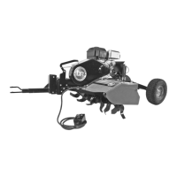
2. Position the left hand Mounting Bracket onto the back
face of Tiller Fender (Figure 4), with mounting tabs
facing in, and replace the hardware you removed in
step 1. Install a 5/16-18 X 1” Hex Head Bolt (on top),
Washer and Nylock Nut (1/2" Wrench) to secure the
Bracket to top of the Tiller Fender. Repeat this step to
install the right hand Mounting Bracket.
Mounting
Bracket
Mounting
Tab
Tiller Fender
Hex Head Bolt,
Washers and
Nylock Nut
Figure 4
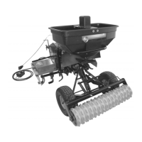
3. Use the top and bottom holes of the Mounting Tubes
on the Hopper/Frame assembly to attach the
assembly to the Spreader Mount Brackets with four
5/16-18 x 1-3/4" Carriage Bolts (1/2" Wrench), four
5/16" Washers and four Wing Knobs (Figure 5). Make
sure that the Carriage Bolt square goes fully into the
square holes of the Spreader Mount Brackets and the
Wing Knobs and Washers are on the Mounting Tube
side.
Wing Knobs
and Washers
Hopper
Assembly
Carriage
Bolts
Hopper
Mounting
Tubes
Figure 5
8 DR
®
ROTO-HOG™ POWER TILLER - OPTIONAL ACCESSORIES