Nylock
Nut
Hopper
Assembly
Angle
Bracket
Bolt,
Washer and
Nylock Nut
Rear
Deflector
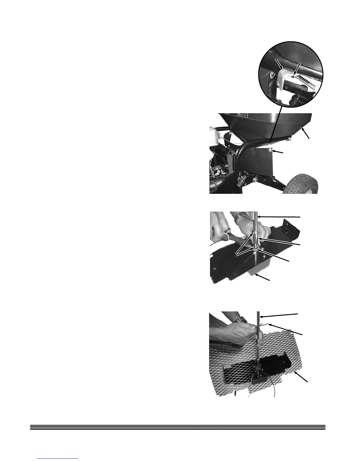
4. Remove two 1/4" Nylock Nuts (7/16" Wrench) from
the Hopper Assembly and position the two Angle
Brackets and secure (hand tight) with the two Nuts
you removed (Figure 6).
5. Position the Rear Deflector onto the Angle Brackets
and secure with two 1/4-20 x 3/4" Bolts, Washers and
Nylock Nuts.
6. Tighten the Nylock Nuts that secure the Angle
Brackets to the Hopper Assembly.
Figure 6
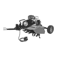
7. Position the Impeller Coupler over the Output Shaft of
the Motor Mount Assembly and secure with 1/8" x 1-
1/4" Cotter Pin (Figure 7).
Motor Mount
Assembly
Impeller
Coupler
Output
Shaft
Cotter
Pins
Impeller
Shaft
NOTE: The Impeller Shaft has three holes in it. It should be
mounted so that the center hole is furthest away from
the Impeller Coupler.
8. Insert the Impeller Shaft into the Impeller Coupler and
secure with 1/8" x 1-1/4" Cotter Pin.
Figure 7
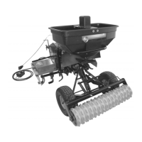
9. Slide the Impeller Shaft through the hole in Spreader
Screen and insert the Agitator Hairpin thru the center
hole in the Impeller Shaft (Figure 8).
Agitator
Hairpin
Spreader
Screen
Impeller
Shaft
Figure 8
CALL TOLL FREE 1-800-DR-OWNER 9