10 DR
®
ROTO-HOG™ POWER TILLER - OPTIONAL ACCESSORIES
Motor Mount
Assembly
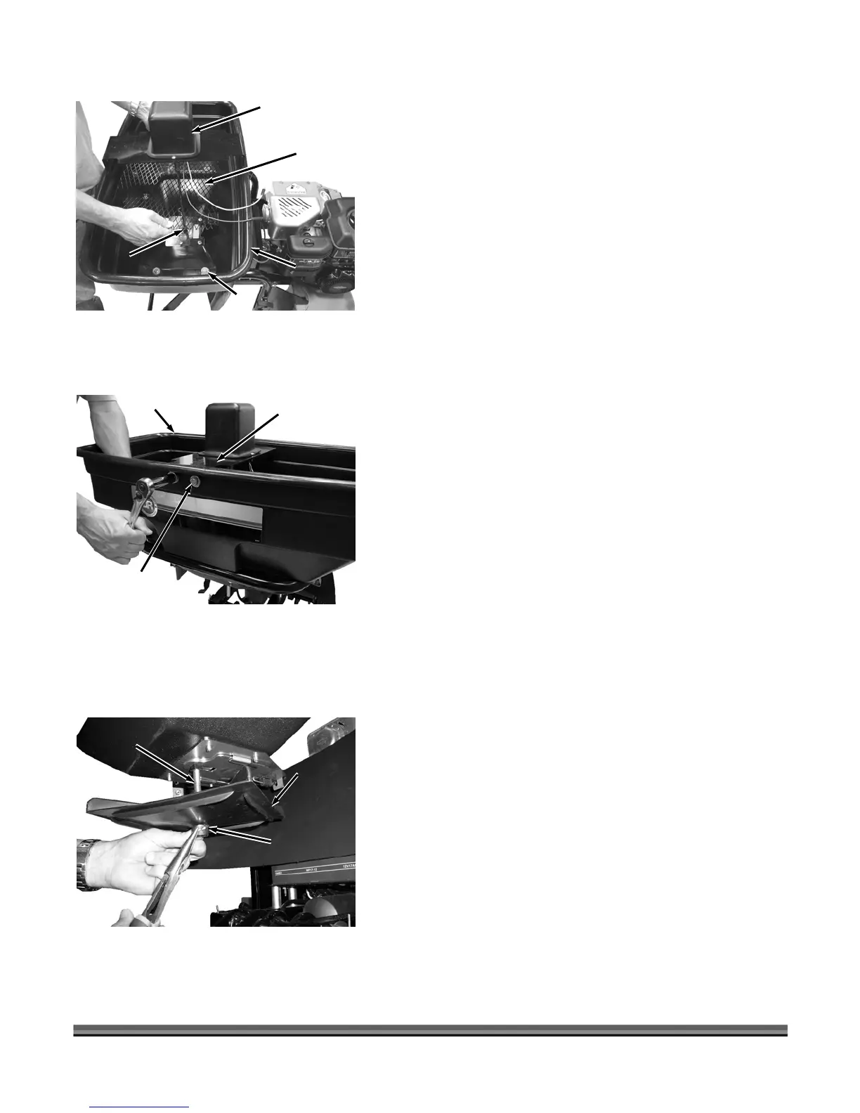
10. Position the Motor Mount assembly with the Spreader
Screen into the Hopper and slide the Impeller Shaft
through the hole in the bottom of the Hopper (Figure
9). Secure the Spreader Screen into the recessed
portion of the Hopper by sliding the edge of the
Screen under the Clips on both sides.
Spreader
Screen
Impeller
Sha
t
Hopper
Clip
Figure 9
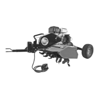
11. Line up the Motor Mount Bracket with holes in
Hopper. Secure Motor Mount Bracket to Hopper with
two 5/16-18 x 1" Hex Bolts, two 5/16" Washers, two
Nylon Washers (against outside of Hopper) and two
5/16" Nylock Nuts (1/2" Wrench) (Figure 10).
Motor M
Bracket
ount
Bolt, Washer,
Nylon Washer
and Nylock
Nut
Hopper
Figure 10
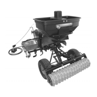
12. Slide the Spreader Impeller onto the Impeller Shaft
with the large fins facing up and secure with 1/8" x 1-
1/4" Cotter Pin (Figure 11).
Impeller
Shaft
Cotter Pin
Spreader
Impeller
Figure 11