HYDRAULIC TORQUE CONVERTER SECTION 7B
Page 27
DRESSTA TD-25M EXTRA
TORQUE CONVERTER
WARNING! Remove the wire used to keep the bearings from falling from the
spider trunnions. If installing a new spider and bearing assembly, remove the soft
iron strap attached to the bearing caps. This will eliminate the possibility of the
straps or wire breaking loose from the caps and causing personal injury when the
engine is running.
4. Install the universal joint (4) between torque converter and transmission. Torque the mounting
bolts to 136 [Nm].
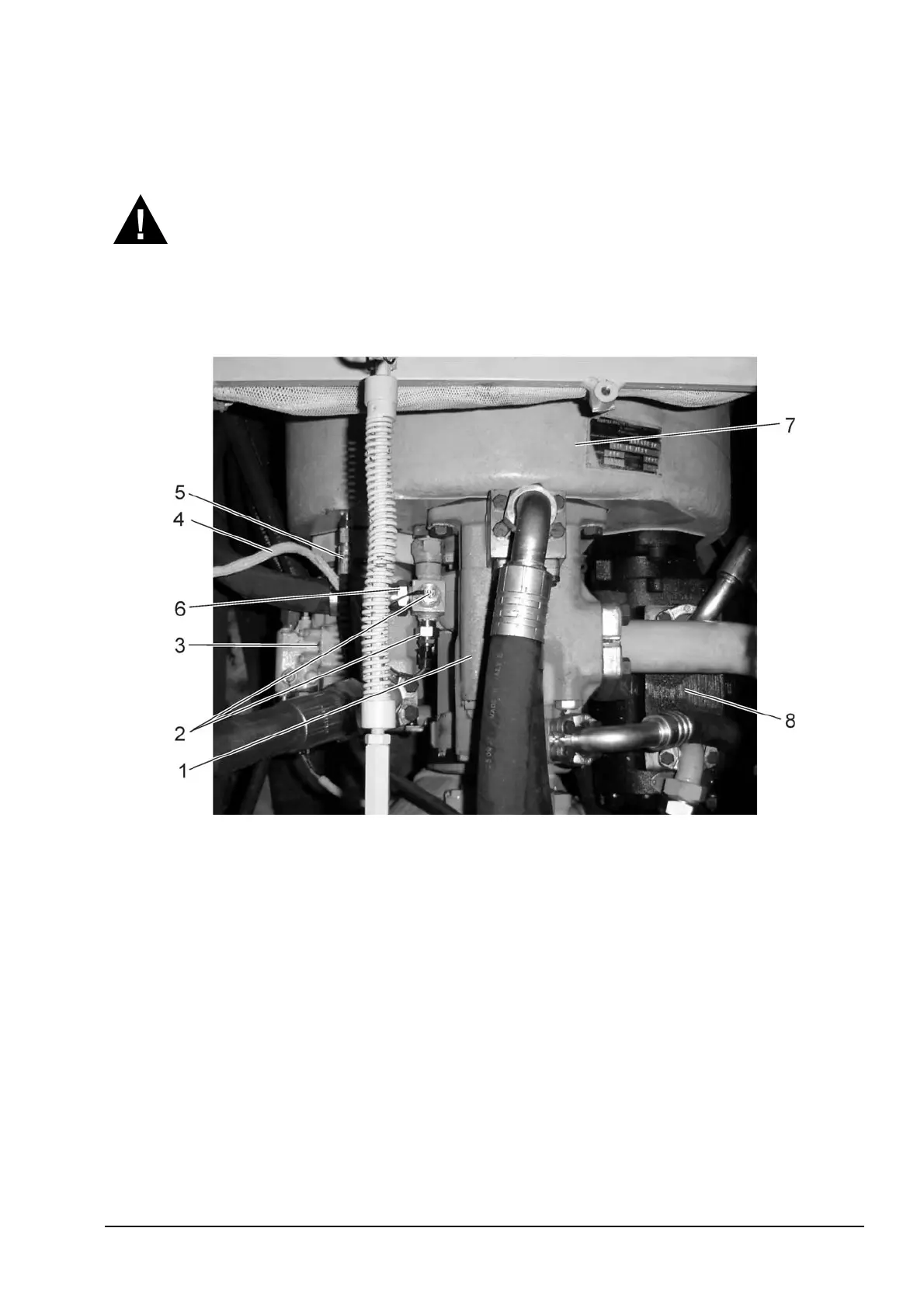
Fig. 7B.8. Upper Torque Converter Reconnecting Points
1. Hydraulic Equipment Pump
2. Torque Converter Oil Temperature Sensors
3. Fan Drive Pump
4. Electrical Harness
5. Torque Converter Breather Hose
6. Oil Cooler Hose
7. Torque Converter
8. Charge and Scavenge Pump
5. Install transmission lube inlet hose (3) and the scavenge suction tube (5) to the transmission.
6. Connect torque converter drain hose (8) to the flywheel housing.
7. Connect the torque converter supply hose (7) to the torque converter (2).
8. Install the fan drive pump (3, Fig. 7B.8). Refer to SECTION 10A for this procedure.
9. Install the charge and scavenge pump (8). Refer to SECTION 7C for this procedure.
10. Install the tee connector with the oil temperature sensors (2) to the torque converter (7).
Connect oil cooler hose (6) to the tee connector. Connect the electrical harness (4) to the
torque converter oil temperature sensors (2).


 To Next Page