SECTION 8 ELECTRICAL
Page 14
TD-25M EXTRA DRESSTA
WIRING DIAGRAM
3A. DRIVE TRAIN CONTROL SYSTEM
3A.1. DRIVE TRAIN CONTROL SYSTEM STRUCTURE
The system will incorporate the following components:
• drive train hydraulic control valve;
• drive train system control lever that incorporates switches and buttons;
• solenoid valves: for gear shifting and steering drive range change (EZ2 and EZ3), (EZL and
EZR), respectively;
• active gear and for range display (D) (two speed steering drive);
• (DTEC) drive train microprocessor controller (ST);
• the (WB) gear presetting mode switch;
• the (WO) auto downshift mode switch;
• magnetic sensors for engine RPM, torque converter output RPM and machine motion
speed, if necessary, being (CS) and (CIW), respectively;
• motion direction pressure switches (WF and WR);
• over voltage & current protection module (EPD).
3A.2. DRIVE TRAIN CONTROL SYSTEM OPERATION PRINCIPLE
a. General
The drive control is done in two different ways. First, hydraulically, with a valve control lever of the
drive control system that actuates suitable valves; the other being a combination of electrical and
electronics with control lever imbedded buttons/ rocker switches assisted with a microprocessor
controller, sensors and switches and solenoid valves.
The motion direction is changed with a control lever shifted forward or rearward while this lever
tilted sideways will steer the machine what is accomplished with selection and steering valves
operation, respectively.
The microprocessor controller is responsible for the following: gear change, speed range change,
gradual turns (different ranges being used for both tracks), auto downshift and gear presetting.
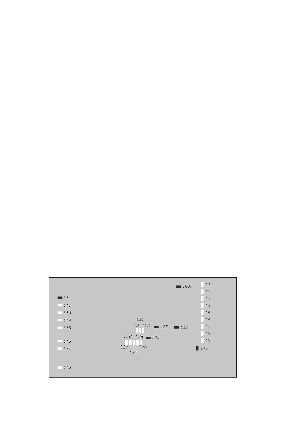
b. Description to signal diodes incorporated in the drive train electronic controller
Fig. 8.1A. LEDs arrangement on the electronic controller


 To Next Page