SECTION 17 MOUNTED EQUIPMENT
Page 6
TD-25M EXTRA DRESSTA
BULLDOZER BLADE
3. INSTALLATION
Blade Only
1. Attach a hoist to the blade lifting eye and lower it into position.
2. Align the pinhole in the pivot of push arm (11, Fig. 17.2) with the hole in push arm bracket (9).
Insert pin (8) through the bracket, aligning the lock holes. Secure the pin with the pin retainer.
Repeat this step on the opposite side of the machine.
3. Machine with Blade Tilt:
Attach a hoist to the tilt cylinder (1, Fig. 17.2) on the right side. Place tension on the hoist.
Slowly raise the tilt cylinder (1) and insert the piston rod ball (6) of tilt cylinder (1) in blade
socket (4) and secure the tilt cylinder cap (5) to the blade socket with the bolts (2) and
washers. Be sure to tighten the bolts with washers evenly to 270 [Nm]. Determine the number
of shims (3) needed to fill the gap between tilt cylinder cap (5) and blade socket (4), then add
one additional shim to provide clearance. Each shim is 0.75 [mm] thick. Remove the bolts (2)
with washers, add the amount of shims (3) required and install and torque the bolts with
washers to 845 [Nm]. Remove the block from under tilt cylinder. Repeat this procedure for the
upper strut on the left side.
4. Machine with Blade Tilt/Pitch:
Attach a hoist to the tilt/pitch cylinder (1, Fig. 17.3) on the left side. Place tension on the hoist.
Slowly raise the cylinder (1) and insert the piston rod ball (6) of tilt/pitch cylinder (1) in blade
socket (4) and secure the tilt/pitch cylinder cap (5) to the blade socket with the bolts (2) and
washers. Be sure to tighten the bolts with washers evenly to 270 [Nm]. Determine the number
of shims (3) needed to fill the gap between tilt/pitch cylinder cap (5) and blade socket (4), then
add one additional shim to provide clearance. Each shim is 0.75 [mm] thick. Remove the bolts
(2) with washer, add the amount of shims (3) required and install and torque the bolts with
washers to 845 [Nm]. Remove the block from under tilt/pitch cylinder. Repeat this procedure
for the tilt cylinder on the right side as described above.
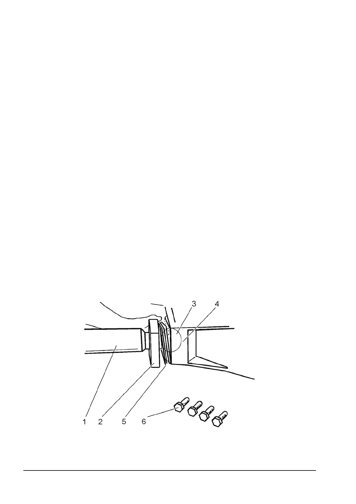
Fig. 17.6. Installing Diagonal Strut to Blade Socket
1. Diagonal Strut
2. Strut Cap
3. Strut Ball
4. Blade Socket
5. Shims
6. Bolts


 To Next Page