MOUNTED EQUIPMENT SECTION 17
Page 5
DRESSTA TD-25M EXTRA
BULLDOZER BLADE
Blade w/Push Arms
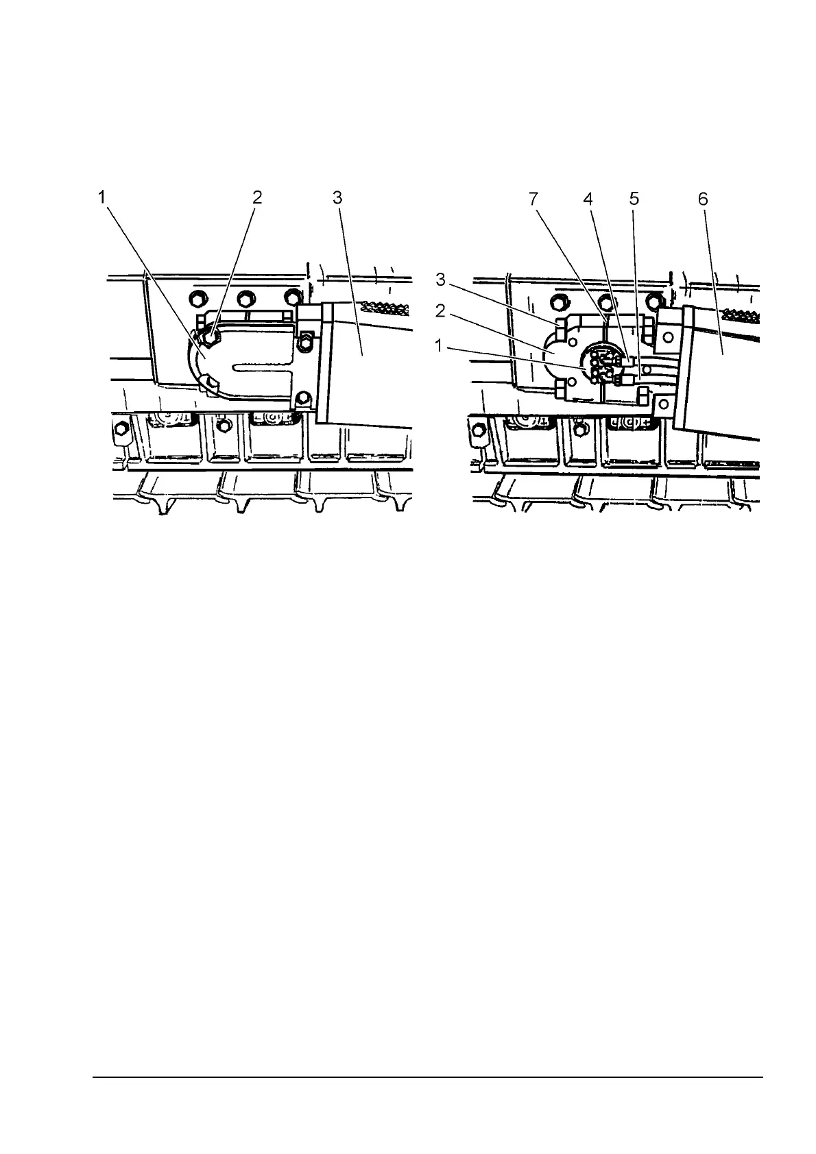
Fig. 17.4. Blade Hoses Connection Cover Fig. 17.5. Push Arm Disconnecting Points
1. Blade Hoses Connection Cover
2. Cover Bolts
3. Push Arm
1. Trunnion
2. Trunnion Cap
3. Bolts
4. Hose
5. Hose
6. Push Arm
7. Shims
1. Lower the blade (1, Fig. 17.1) to the ground and install blocks under the rear end of the push
arms (23 and 28).
2. Disconnect the lift cylinders at the blade (7, Fig. 17.2) by removing the pin locking hardware
and drive out the mounting pins from lift cylinder brackets (10). Hydraulically retract the rods
and secure the cylinders to the radiator guard with the cylinder hangers.
3. Unscrew bolts (2, Fig. 17.4) and remove blade hoses connection cover (1) from push arm (3).
Repeat this step on the opposite side of the machine.
4. Machine with Blade Tilt: Disconnect hoses (4 and 5, Fig. 17.5) from right trunnion (1).
5. Machine with Blade Tilt/Pitch: Disconnect hoses (4 and 5, Fig. 17.5) from right and left
trunnions (1).
6. Unscrew two trunnion cap bolts (3, Fig. 17.5) and remove cap (2) with shims (7) from push
arm (6). Repeat this step on the opposite side of the machine.
7. Back the machine out from between the push arms.
8. Reassemble shims (7, Fig. 17.5) and caps (2) to the push arms (6) and secure with bolts (3) to
prevent their damage or being lost.


 To Next Page