POWER SECTION 12
Page 13
DRESSTA TD-25M EXTRA
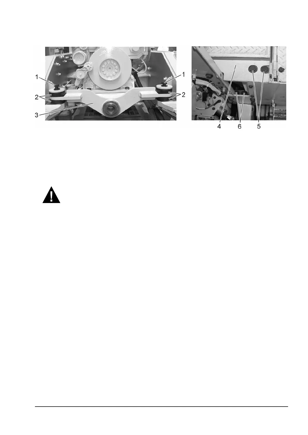
Fig. 12.11. Front and Rear Engine Brackets
1. Bolts
2. Rubber Bushings
3. Front Engine Bracket
4. Bar
5. Bolts
6. Engine Bracket Bolts (rear)
NOTE: Whenever possible, a load adjusting sling should be used to remove the engine. With an
adjusting sling, engine can be tilted or leveled as required, reducing job time, effort and hazard.
WARNING! The wet weight of QSX15 engine with torque converter is 2000 [kg].
The engine lifting equipment must be designed to safely lift the engine.
37. Raise engine with torque converter up (approximately 10 [cm]. Make a visual inspection around
engine to be sure that all disconnects required for engine removal have been made. Guide the
engine with torque converter forward. Then lift and turn assy round vertical axis until torque
converter with pumps is outside of machine frame.
38. Position engine into the suitable engine support stand.
NOTE: After engine is removed from machine, it should be placed on a prepared block frame
support.
39. Install the hoist to the torque converter and pumps. Remove bolts securing torque converter
to the flywheel housing and separate it.
6. ENGINE REPAIR
For detailed information pertaining to maintenance or engine repair, refer to the Engine Operation
and Maintenance Manual QSX15 Engines, Bulletin No 3666423, Troubleshooting and Repair
Manual QSX15 Engines, Bulletin 3666239 and Troubleshooting Repair Manual Electronic Control
System QSX15 Engines, Bulletin No.3666259.


 To Next Page