SECTION 12 POWER
Page 12
TD-25M EXTRA DRESSTA
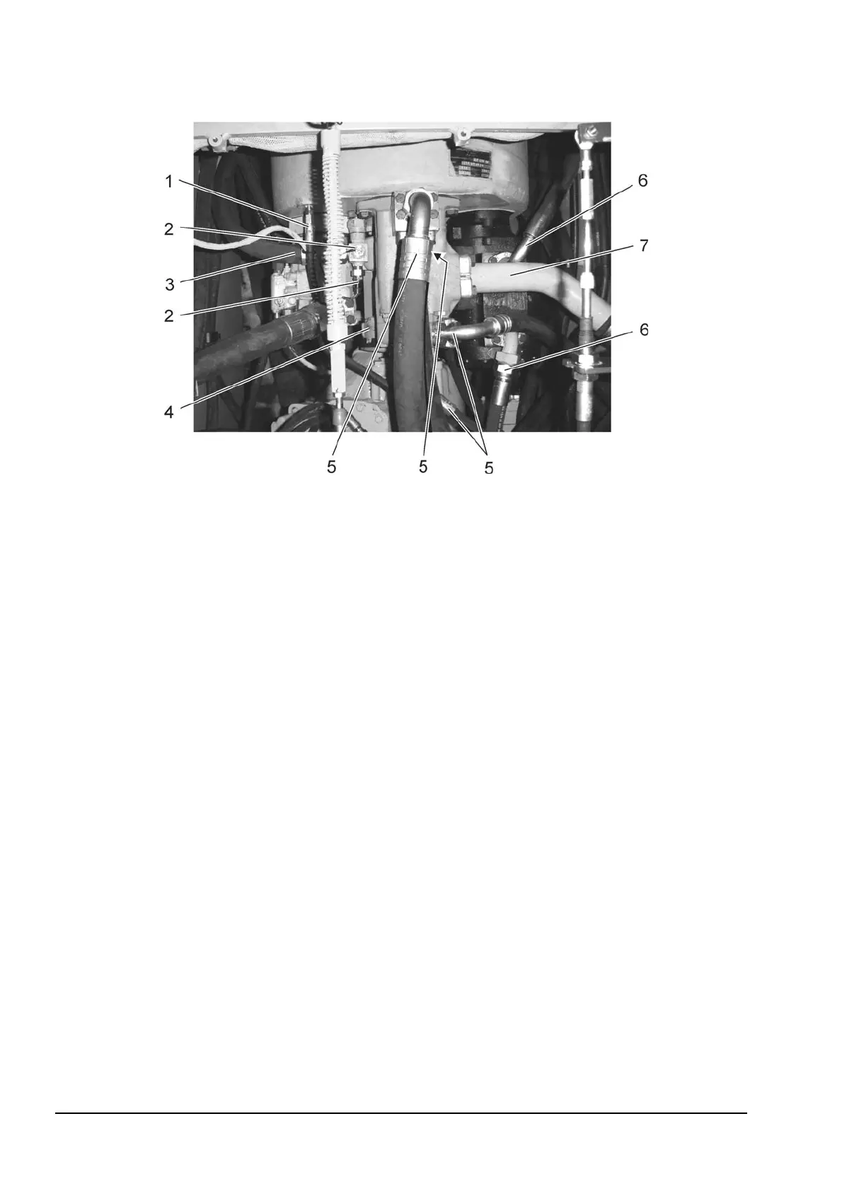
Fig. 12.10. Torque Converter Disconnecting Points (upper side)
1. Vent Hose
2. Oil Temperature Sensors
3. Hose (outlet)
4. Drive Shaft
5. Hoses (outlet)
6. Hoses (outlet)
7. Tube (inlet)
24. Disconnect wires from the oil temperature sensors (2, Fig. 12.10).
25. Remove vent hose (1) from the torque converter.
26. Remove outlet hose (3) from the torque converter.
27. Remove two bolts (2, Fig. 12.9) securing fan drive system pump (1). Separate pump from the
plate connector of the torque converter and wire pump to the pod.
28. Remove bolts securing drive shaft (4, Fig. 12.10) to the torque converter output shaft.
29. Drain the hydraulic reservoir as described in Operator’s Manual.
30. Remove hoses (5) from the hydraulic pump. Wire hoses in upright position.
31. Remove tube (7) from the hydraulic system pump.
32. Remove hoses (6) from the drive train system pump. Wire hoses in upright position.
33. Unscrew bolts (1, Fig. 12.11) securing front engine bracket (3) to frame.
34. Remove bolts (5) (both sides) and remove bar (4) to gain access to the rear engine
brackets.
35. Unscrew bolts securing rear engine brackets (6) to frame on both sides.
36. Install an engine lifting attachment to engine lifting brackets (4, Fig. 12.5) and (10, Fig.12.7).
NOTE: Engine flywheel housing is critically close to the equalizer bar tunnel. For this reason it is
hard to dismount torque converter off engine. We recommend dismounting the engine complete
with the torque converter.


 To Next Page