SECTION 7B HYDRAULIC TORQUE CONVERTER
Page 26
TD-25M EXTRA DRESSTA
TORQUE CONVERTER
9. INSTALLATION
IMPORTANT: All gaskets and any collapsed hoses or damaged connections must be replaced
with new. Whenever a sealing ring is required at a disconnected line, it is recommended that
a new sealing ring be installed.
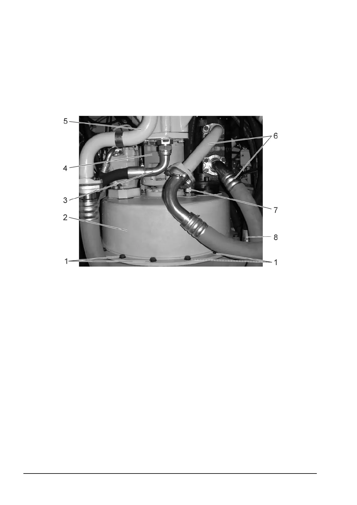
Fig. 7B.7. Lower Torque Converter Reconnecting Points
1. Mounting Bolts
2. Torque Converter
3. Transmission Lube Inlet Hose
4. Universal Joint
5. Scavenge Suction Tube
6. Charge and Scavenge Pump Outlet Hoses
7. Torque Converter Supply Hose
8. Torque Converter Drain Hose
1. Remove the covering from the engine flywheel housing. If flywheel gear ring (36, Fig. 7B.1
or Fig. 7B.2) was replaced install new gear ring and secure with bolts applying LOCTITE #243.
Torque bolts to 83 – 101 [Nm].
2. Thoroughly clean the mating surfaces of the torque converter housing and the engine flywheel
housing. Install a new O-ring on the converter housing flange.
3. Install of 100 to 130 [mm] two aligning studs at 10 and 2 o'clock positions in flywheel housing.
Fasten the hoist and raise the torque converter into position on the aligning studs. Move the
torque converter toward the engine until the torque converter drive housing gear meshes with
the drive gear in the flywheel housing. Secure the torque converter to the flywheel housing.
Torque the bolts (1, Fig. 7B.7) with washers to 110 [Nm].
IMPORTANT: As the converter housing enters the flywheel housing, be sure the O-ring is properly
seated in the groove of the converter housing.


 To Next Page