HYDRAULICS SECTION 10
Page 13
DRESSTA TD-25M EXTRA
TEST AND ADJUSTMENT
Blade Lift and/or Ripper Relief Valve Pressure Test
Open the door from right side and connect an 40 [MPa] gauge with quick coupler (see SERVICE /
SPECIAL TOOLS in this Section) to the quick disconnect fitting (2, Fig. 10.7) and proceed as
follows.
NOTE: One spool control valve only; because of relief poppets in blade lift cylinders, raise supply
line must be capped or piston rod must be stopped in the middle position. Lower blade to ground.
Open the door from right side and disconnect end raise hose from control valve (1, Fig. 10.7).
Install a plug with O-ring and secure with hose split flanges at control valve. Cap disconnected
hose.
1. ONE SPOOL VALVE; Once operating temperature is reached, run engine at full throttle and
slowly move blade lift control lever to raise position. Read and record pressure on gauge at
which relief valve unloads.
2. THREE SPOOL VALVE; Once operating temperature is reached, run engine at full throttle and
slowly move ripper lift control level into a power position until cylinders are in extreme position.
Read and record pressure on gauge at which relief valve unloads. Repeat this procedure with
ripper pitch control lever.
3. Repeat Step 1 or 2 with engine at low idle. Read and record pressure on gauge at which relief
valve unloads.
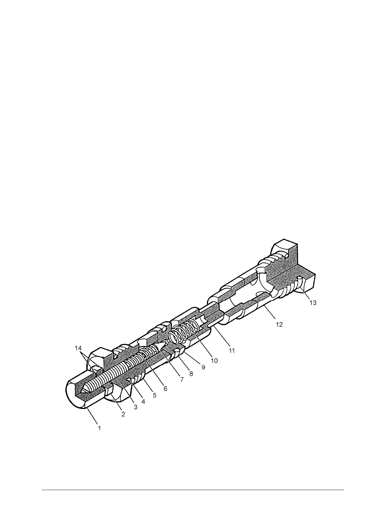
Fig. 10.9. One or Three Spool Control Valve Relief Valve
1. Acorn Nut
2. Jam Nut
3. Adjusting Screw
4. O-Ring
5. End Cap
6. Poppet Spring
7. Relief Poppet
8. O-Ring
9. Pilot Relief Seat
10. Check Valve Spring
11. Check Valve
12. End Cap
13. O-Ring
14. Washer


 To Next Page