COOLING SYSTEM SECTION 6
Page 7
DRESSTA TD-25M EXTRA
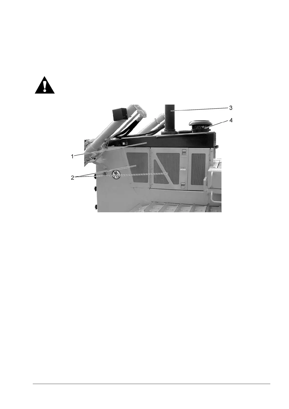
4. Remove the exhaust tube assy (3, Fig. 6.2).
5. Remove bolts and disassemble side enclosure (2).
6. Remove bolts securing the hood (1). Remove the hood assembly from the machine.
7. Attach a suitable lifting device to the crankcase guard, remove the hardware and lower the
guard on the ground to give the access to the bottom radiator mounting points.
WARNING! This procedure requires extreme caution. Use suitable blocking
equipment while under confines of machine.
Fig. 6.2. Hood and Engine Enclosure
1. Hood 3. Exhaust Tube
2. Side Enclosure 4. Air Precleaner
8. Drain coolant from cooling system. Refer to Operator’s Manual.
9. Loosen the clamp and remove vent hose (5, Fig. 6.3) from the auxiliary tank and attach it to
engine.
IMPORTANT: Disconnected lines must be capped with the correct size plastic caps or clean corks.
Openings must never be plugged with rags. This practice could easily introduce dirt or lint in to
critical components of the system.
10. Disconnect wire harness connector from the coolant level switches (6, Fig. 6.3) and
(3, Fig. 6.7), and secure it to frame.
11. Loosen the clamp and remove coolant fill hose (3, Fig. 6.3) from the auxiliary tank.
12. Remove hydraulic hose (2) from drive train oil cooler. Secure hose in an upright position to
frame.
13. Tag and remove hose (7) from fan drive hydraulic motor oil cooler. Secure hose in an upright
position to frame.
14. Loosen the clamps and remove coolant tube (4) between the radiator and engine outlet.


 To Next Page