19
DEHUMIDIFIER INSTALLATION, OPERATION, AND MAINTENANCE MANUAL
INSTALLATION
RL-3, RL-4, and RL-6 mounting
90-2020
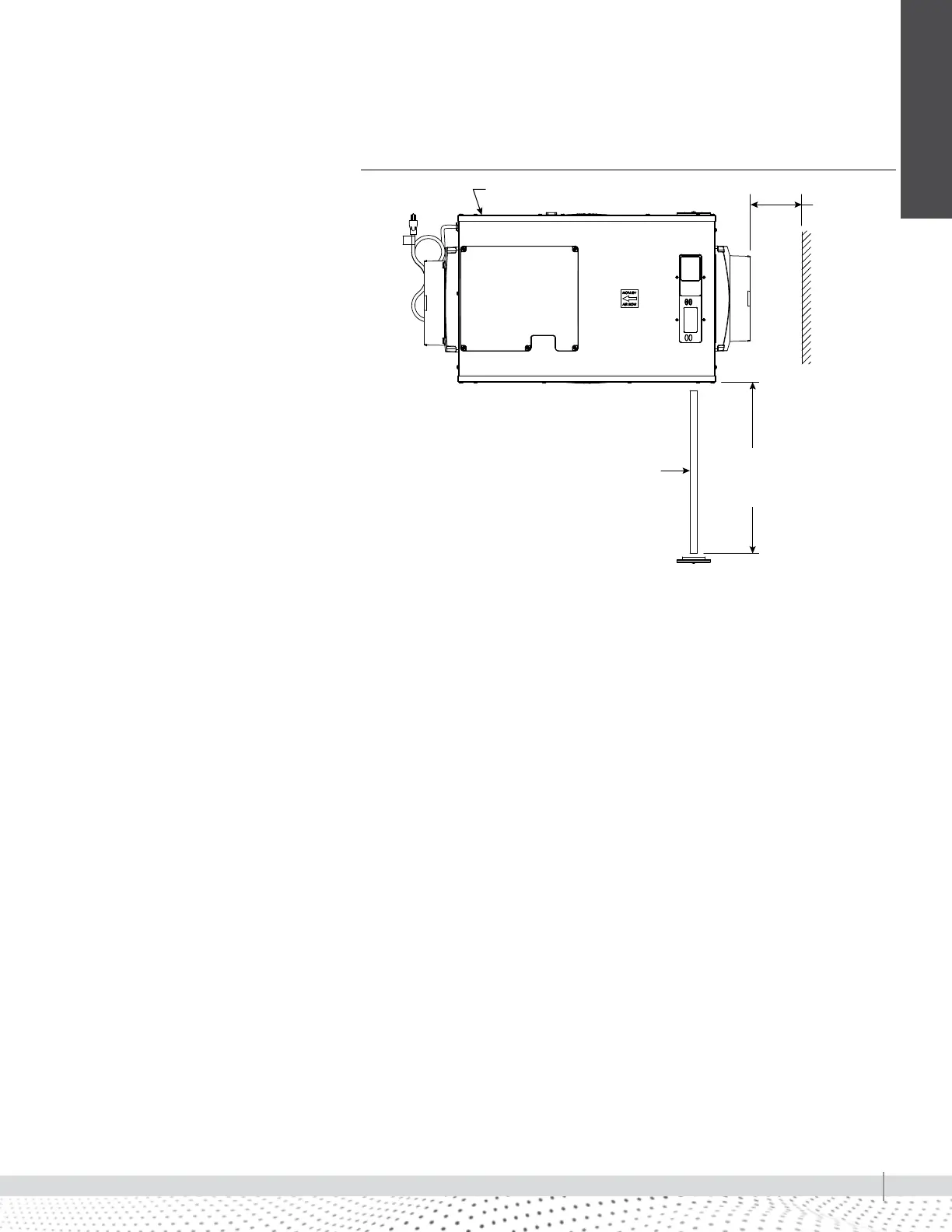
MODEL RL-3, RL-4 AND RL-6 LOCATION
CONSIDERATIONS
• Allow sufficient clearance for filter
removal and to prevent airflow
obstruction
• Electrical service access will
require the removal of the side
panel shown. Allow sufficient
space for service on this side of
the unit.
• When suspending the unit, a
condensate pan with float switch is
recommended to prevent any leaks
that may occur due to unforeseen
drain line obstructions.
FIGURE 19-3: RL-3, RL-4 AND RL-6 FILTER ACCESS CLEARANCE
TOP
18 (457 mm)
minimum
clearance for
proper air
flow
18" (457mm) minimum
Model RL-6: 20 (508 mm)
minimum clearance for filter
(either side)
Filter
Electrical service access this side