EasyManua.ls Logo

DROPSA VIP5 User Manual

Default Icon
29 pages
To Next Page IconTo Next Page
Page #1 background imageLoading...
Page #1 background image
VIP5: Lubrication System
Controller
Control system for small and medium size
Lubrication Systems
Software Version 3.0
Quickstart Guide
User Operating and Maintenance
Manual
Original text translation
Warranty Information
CONTENT
1. INTRODUCTION
2. PRODUCT FEATURES
3. DESCRIPTION OF OPERATING PROCEDURES
4. FIXING AND INSTALLATION DETAILS
5. INPUTS/OUTPUTS
6. OPERATOR INTERFACE FRONT PANEL
7. OPERATING MODE
8. CYCLE MONITORING
9. SETUP PROGRAMMING
10. PROBLEMS AND SOLUTIONS
11. TECHNICAL SPECIFICATIONS
12. MAINTENANCE PROCEDURES
13. DISPOSAL PROCEDURES
14. ORDERING INFORMATION
15. MOVING AND SHIPPING
16. OPERATING PRECAUTIONS
17. WARRANTY
18. REVISIONS
19. DECLARATION OF COMPLIANCE
20. DISTRIBUTORS
Manual compiled in accordance with Directive C2094IE WK 20/11
06/42 CE
http://www.dropsa.com
Question and Answer IconNeed help?

Do you have a question about the DROPSA VIP5 and is the answer not in the manual?

DROPSA VIP5 Specifications

General IconGeneral
BrandDROPSA
ModelVIP5
CategoryController
LanguageEnglish

Summary

Quickstart Guide

10 STEPS TO SETUP YOUR VIP5 Controller

Provides a step-by-step guide for initial setup of the VIP5 Controller.

Introduction

Definition of Lubrication and Standby Phase

Defines key operational phases like Lubrication Phase and Standby Phase.

Product Features

Description of Operating Procedures

Control System Operating Principles

Explains the operating principles for CYCLE and PULSE control systems.

Prelube Phase

Describes the pre-lubrication cycle triggered on power-on or reset.

Lubrication Phase

Details the lubrication cycle, including activation, control, delay, and wait times.

Standby Phase

Explains the system's inactive period awaiting the next lubrication phase.

Flow Mode Operating Principles

Describes the VIP5's function as a flow monitoring device.

Fixing and Installation Details

Un-packing Instructions

Guidelines for safely unpacking the VIP5 unit from its shipping box.

Installation Guidelines

Instructions for physically securing and cabling the VIP5 controller.

Inputs and Outputs

Electrical Connections Overview

Details the M1 and M2 terminal strip connections for inputs and outputs.

Wiring Examples

Provides visual examples of common wiring configurations for the VIP5.

Battery Activation for Real Time Clock

Explains how to activate the battery for date/time and save functions.

Wiring Precautions

Safety advice and precautions to follow when carrying out wiring.

Operator Interface Front Panel

Panel Layout and Status Table

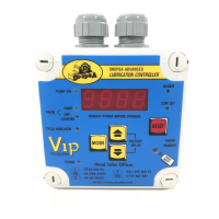
Identifies front panel components, LEDs, and their operational status.

Operating Mode

CYCLE Mode Operation

Describes operation where a cycle sensor determines lubrication phase completion.

PULSE Mode Operation

Describes operation where Standby and Lubrication phases are determined by an external counter.

FLOW Mode Operation

Describes operation as a flow monitoring and display device.

Prelube Functionality

Details the pre-lubrication cycle triggered on power-on or reset.

Cycle Monitoring

Monitoring Options Overview

Lists the four possible cycle monitoring options available.

Timer - Time Only Monitoring

Operation based solely on a preset timer value for lubrication cycles.

PS - Pressure Switch Monitoring

Monitoring using a pressure switch, typically for injector systems.

SEP - Series Progressive Monitoring

Monitoring for progressive systems using cycle switch feedback.

DL - Dual Line Monitoring

Monitoring using two pressure switches for dual line systems.

Dual Line Directional Valve Control Notes

Advice on controlling directional valves in dual line lubrication systems.

Setup Programming

Navigating the Setup Menu

Guide to navigating through the VIP5 setup menus and parameters.

Basic vs. Extended Menu

Overview of the Quick setup (Basic) and comprehensive (Extended) menus.

Parameters and Values

Special Functions

Details on special functions like LCD contrast, flow totalizer, and time/date settings.

Problems and Solutions

Alarm Code Table

Lists and explains possible alarm codes and troubleshooting steps.

Restart and Reset Procedures

Procedures for handling alarms and resetting the VIP5 controller.

Remote Coded Alarm Function

How to use the alarm relay for coded alarm signals to a PLC.

Technical Specifications

Maintenance Procedures

Disposal Procedures

Ordering Information

Moving and Shipping

Operating Precautions

Warranty

Revisions

Declaration of Conformity

Distributors

Related product manuals