Copyright 2010 Baker Hughes Company.
English–PACE Calibration Manual | 9
Note: You do not need to connect the Supply+ and Outlet port for this connection.
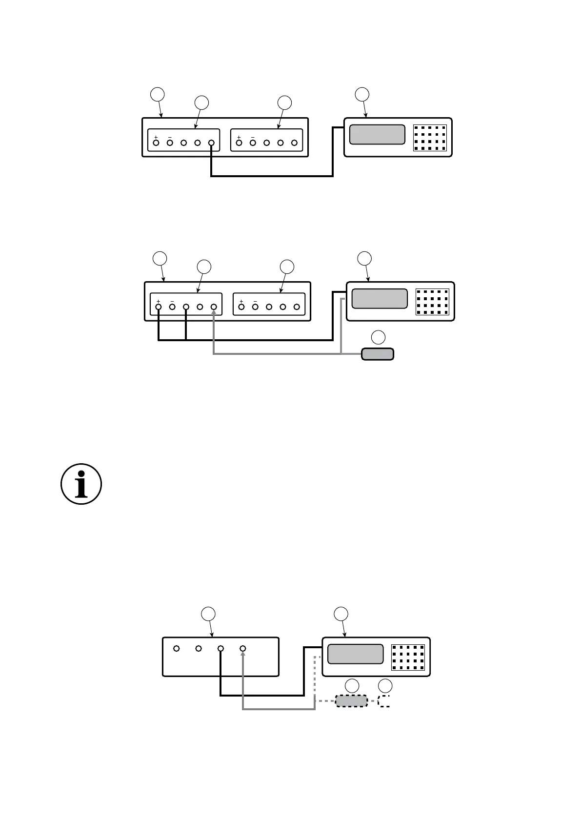
Figure 8: Connection for Barometric Sensor Calibration
5.4 PACE Controller Connection for Low Pressure Calibration
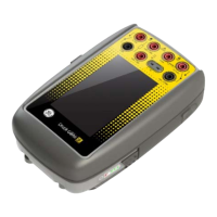
Figure 9: Connection for Low Pressure Measurement
5.5 PACE Indicator Connection for Input Sensor Calibration
1. Connect the output of the pressure calibration standard to the PACE input port.
Note: For gauge sensor calibration, apply positive and negative gauge pressures to the
PACE input port.
2. To attenuate changes in atmospheric pressure, or changes due to drafts, connect the PACE
reference port to the pressure calibration standard reference port. If a reference connection
is unavailable, fit snubber IO-SNUBBER-1 to the PACE reference port.
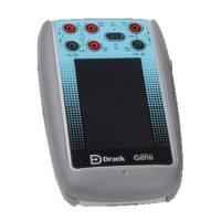
Figure 10: Connection for Input Sensor Calibration
1 PACE Pressure Controller (seen from rear). 2 Control Module 2.
3 Control Module 1. 4 Pressure calibration standard.
1 PACE Pressure Controller (seen from rear). 2 Control Module 2.
3 Control Module 1. 4 Pressure calibration standard.
5 Low pressure differential connection kit
(IO-DIFF-KIT-LP).
INFORMATION For optimum performance, connect the PACE reference port
to the pressure calibration standard with a snubber to atmosphere. This is not
normally necessary for pressure ranges of 7 bar and above.
1 PACE Pressure Indicator (seen from rear). 2 Pressure calibration standard.
3 Snubber 4 Atmosphere.
SUPPLY OUTLET VENT REF SUPPLY OUTLET VENT REF
1 4
2 3
SUPPLY OUTLET VENT REF SUPPLY OUTLET VENT REF
1 4
2 3
5