Section 2: Installation
Assigning Keypad Zones
When using keypad zone inputs, each input used must be assigned a zone number in Installer Programming.
First, ensure that you have enrolled all installed keypads into the desired slots (See "[902] Add/Remove Modules" on page
118). Next, assign keypad zones by entering programming section [861]-[876], subsection 011 for keypads 1-16. Enter a 3-
digit zone number for each of the keypad zones. This number must be programmed into the slot location that the keypad is
assigned to.
Note: If a keypad zone input is assigned to zone number 1 to 8, the corresponding zone cannot be used on the main control
panel.
Once the keypad zones are assigned, you must also program zone definitions and zone attributes. See "[001] Zone Types"
on page 64 and See "Zone Setup" on page 64.
2.4.6 HSM2955 Wiring
For wiring information refer to HSM2955 Installation manual #29008435xxx.
2.4.7 Alternate Communicator Wiring
See Alternate Communicator installation manual.
2.4.8 Zone Wiring
Power down the alarm controller and complete all zone wiring.
Zones can be wired to supervise normally open devices (e.g., smoke detectors) or normally closed devices (e.g., door con-
tacts). The alarm panel can also be programmed for single end-of-line or double end-of-line resistors.
Zone programming is done using the following programming sections:
l [001] selects zone definition
l [013] Opt [1] for normally closed or EOL; Opt [2] for SEOL or DEOL
l [201 - 208] partition assignment.
Observe the following guidelines when wiring zones:
l For UL listed installations use SEOL or DEOL only
l Minimum 22 AWG wire, maximum 18 AWG
l Do not use shielded wire
l
Do not exceed 100Ω wire resistance. Refer to the following table:
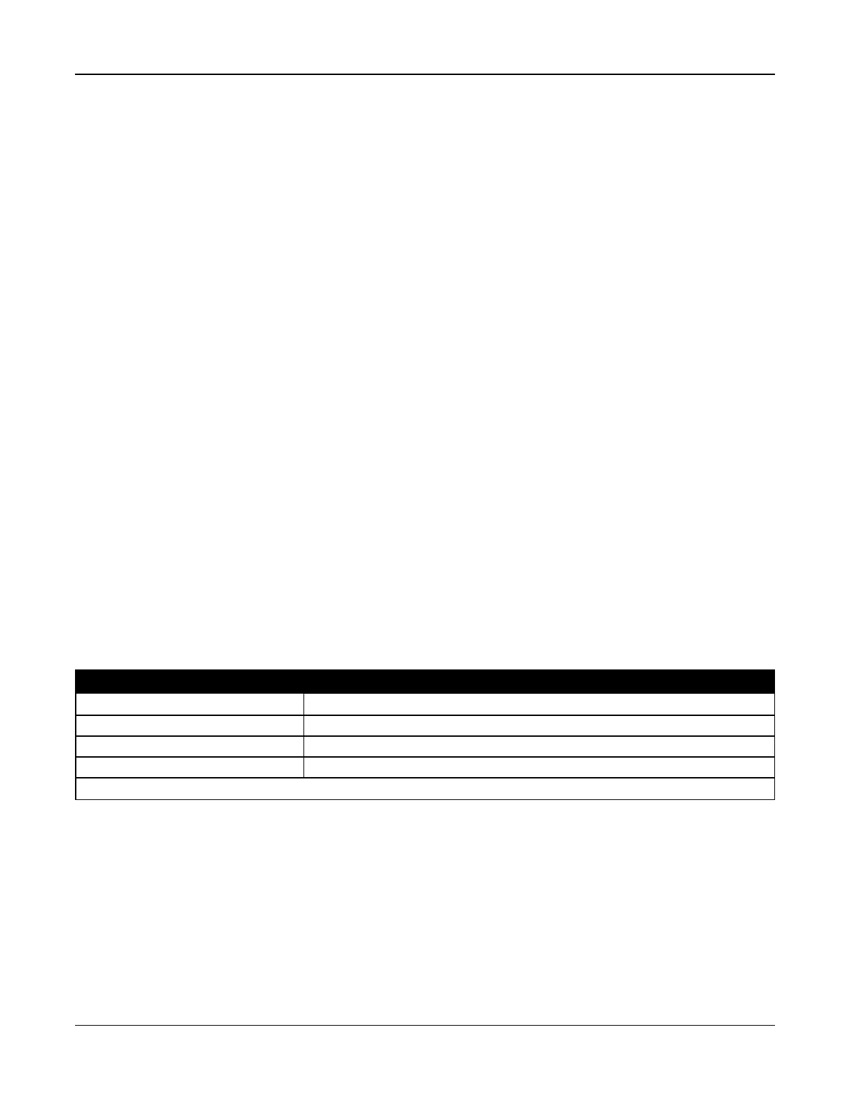
Table 2-4 Burglary Zone Wiring Chart
Wire Gauge Maximum Length to EOL Resistor (ft/meters)
22 3000 / 914
20 4900 / 1493
19 6200 / 1889
18 7800 / 2377
Figures are based on maximum wiring resistance of 100
Ω.
Normally Closed
Connect hardwired devices to any Z terminal and any Com terminal. Wire normally closed devices in series.
Note: For UL Installations, do not use normally closed loops.
- 19 -