Section 2: Installation
To enable DEOL supervision, program section [013], option [1] to OFF and option [2] to ON.
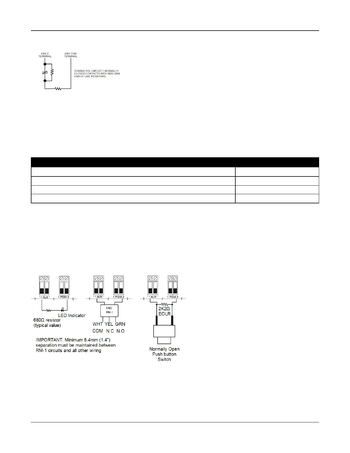
Figure 2-11 DEOL Wiring
Note: If the DEOL supervision option is enabled, all hardwired zones must be wired for DEOL resistors, except for Fire and
24 Hour Supervisory zones. Do not use DEOL resistors for Fire zones or 24 Hour Supervisory zones.
Note: Do not wire Fire zones to keypad zone terminals if the DEOL supervision option is selected.
Note: This option can only be selected if N/C detection devices or contacts are used. Only one N/C contact can be con-
nected to each zone.
The following table shows zone status under certain conditions for DEOL:
Table 2-7 DEOL Loop Status
Loop Resistance Loop Status
0
Ω
(shorted wire, loop shorted) Fault
5600
Ω
(contact closed) Secure
Infinite (broken wire, loop open) Tamper
11200
Ω
(contact open) Violated
2.4.9 PGM Wiring
Min/max operating voltages for devices, sensors and modules is 9.5VDC - 14VDC.
PGMs switch to ground when activated from the alarm controller. Connect the positive side of the device to the AUX+ ter-
minal and the negative side to a PGM terminal.
PGM 1, 3, 4 supply up to 50mA; PGM 2 supplies up to 300mA.
A relay is required for current levels greater than 50mA or 300mA. PGM2 can also be used for 2-wire smoke detectors, 24-hr
burglary input alarm.
Note: Use SEOL resistors on Fire zones only.
Figure 2-12 LED Output with Current Limiting Resistor and Optional Relay Driver Output.
UL Compatibility ID For FSA-210B Series is: FS200
Note: For ULC listed installations, use FSA-210A and FSA-410A series.
- 21 -