G E T T I N G S T A R T E D
11
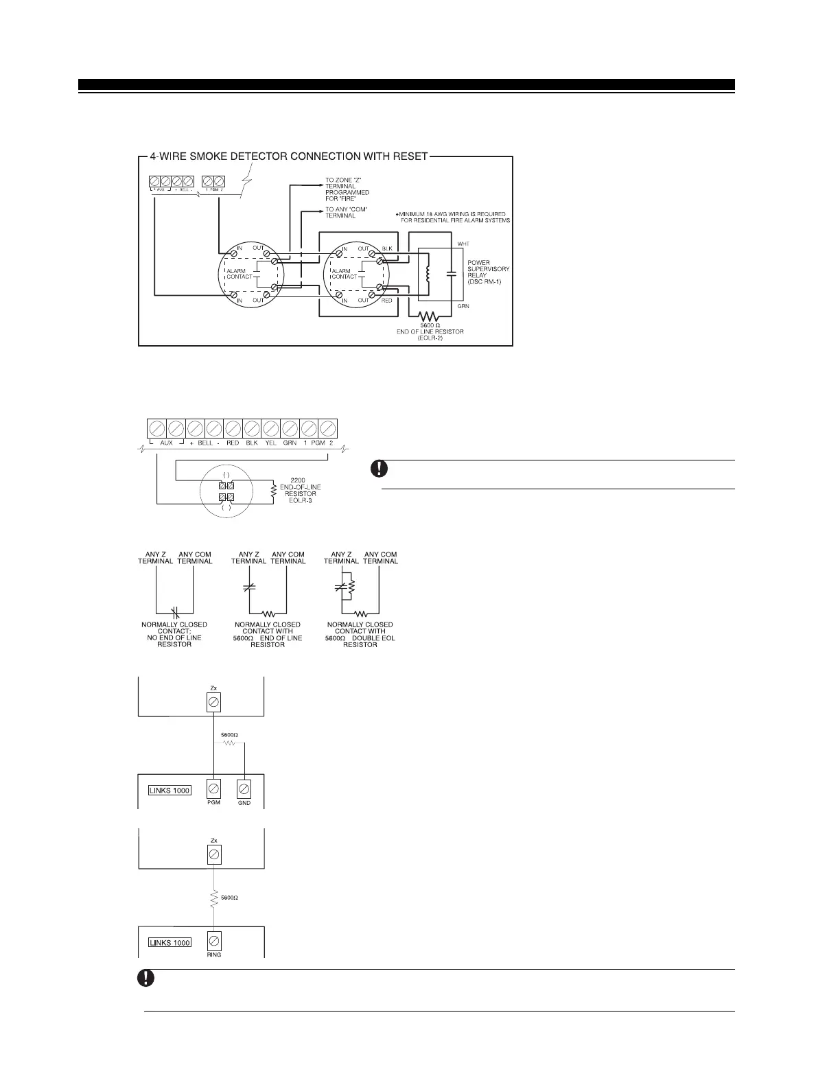
2.9.4 Fire Zone Wiring - 4 wire Smoke Detectors
All zones defined as Fire
(See Section 5.1 “Zone Definitions”)
must be wired according to the following diagram:
For a complete description of how fire zones operate,
see Section 5.1 “Zone Definitions”.
2.9.5 Fire Zone Wiring - 2 wire Smoke Detectors
If PGM2 has been programmed for 2 Wire Smoke Detector connection
(See Section 5.10 “PGM Output”),
the detectors must be wired according to the following diagram:
+
Ω
+
-
For a complete description of how fire zones operate,
see
Section 5.1 “Zone Definitions”.
If PGM2 is programmed for 2 wire smoke support, Jumper
CON1 on the main board must be removed.
2.9.6 Keyswitch Zone Wiring
Zones may be programmed to be used as keyswitch
arming zones and must be wired according to the
following diagrams:
For a complete description of how keyswitch zones
operate,
see Section 5.1 “Zone Definitions”.
2.9.7 LINKS Supervisory (24 Hour Supervisory)
When using the LINKS1000 cellular communicator, any main board zone
may be configured for LINKS Supervision. Program this zone as zone type
[09], 24 Hour Supervisory in section [001].
With a 24 Hour Supervisory zone, if the LINKS1000 experiences a trouble, the
zone will be violated, causing the panel to report the event to the central
station. This type of zone
always
requires a single EOL resistor (5600Ω).
Wire this zone according to the diagram.
2.9.8 LINKS Answer
If the LINKS1000 cellular communicator is being used a zone may be
configured for LINKS Answer to allow downloading to be performed in the
event of phone line failure.
When the LINKS receives a phone call it will activate the RING terminal on the
LINKS circuit board. This terminal can be used to violate a zone programmed
as LINKS Answer
(See Section 5.1 “Zone Definitions”)
, causing the panel to
seize the phone line and begin communication with the downloading
computer.
The zone programmed as LINKS Answer ALWAYS requires a single EOL resistor
(5600Ω) and must be wired according to this diagram.
The LINKS Answer zone is only required for downloading to the panel via the LINKS.
When using the LINKS, Busy Tone Detection must not be used.
Keypad zones cannot be used for 24 Hour Supervisory or LINKS Answer.