P R O G R A M D E S C R I P T I O N S
31
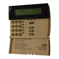
Keypads can be assigned to work on either partition or can be assigned for Global operation
(See
Section 2.6 “Keypad Assignment”).
Each partition can be programmed to report using a different Account Number
(See Section 5.5
“Communicator - Account Numbers”).
Some of the Programmable Output options are also selectable by Partition
(See Section 5.10 “PGM Outputs”).
The Partition 2 Enable option must be programmed before Partition 2 will operate.
At default zones 1 through 8 are assigned to Partition 1. If additional zones are being used or the
application requires two Partitions zones must be enabled to operate on the correct Partition.
Zones programmed as Null must be removed from both Partitions (See Section 5.1 “Zone Definition).
○○○○○○○○○○○○○○○○○○○○○○○○○○○○○○○○○○
Partition 2 is Enabled ............................................. Section [201], Option [1]
Partition 1 Zone Assignments................................ Section [202] to [205]
○○○○○○○○○○○○○○○○○○○○○○○○○○○○○○○○○○
Partition 2 Zone Assignments................................ Section [206] to [209]
5.10 PGM Outputs
There are 3 different types of Programmable Outputs available. They are listed as follows:
• PGM1 and PGM2 on the main board
• 8 low current outputs available with the PC5208 Output Module
• 4 high current outputs available with the PC5204 Power Supply/Output Module
Programming any of the PGM Outputs is a two step process. First an option from the below list must be
selected for the PGM Output. Second the PGM Attributes must be selected. The following is a list of the
PGM Output Options and PGM Attributes.
5.10.1 PGM Output Options
[01] Burglary and Fire Bell Output The PGM output will activate when the alarm output is active and will
turn off when the alarm output is silenced. If the alarm output is pulsing the PGM output will pulse as well.
This output does not follow the pre-alert for delayed fire zones.
[02] for future use
[03] Sensor Reset ([✱] [7] [2])
This output will normally be active (switched to ground).
This option is used to reset power for latching smoke detectors. The output will deactivate for five
seconds when the [
✱] [7] [2] command is entered (see Section 3.4 “[✱] [7] Output Functions”). The
keypad buzzer will not sound for the five second period.
Please refer to the Control Panel Wiring Diagram in this manual for wiring instructions.
Only ONE of options [03] Sensor Reset, [04] 2-Wire Smoke and [20] [
✱
] [7] [2] Command Output
Option #2 may be programmed on the same system.
[04] Two-Wire Smoke Support (PGM2 Only) PGM2 may be used in conjunction with two-wire smoke detectors.
PGM Output Attributes for PGM2 when used for two wire smoke detector support must remain at
default, Attribute 1, 2 and 3 ON.
Do not program any PGM output other than PGM2 for two-wire smoke detector support.
Refer to the Hook-Up diagram in this manual for wiring instructions
(See Section 2.9.5 “Fire Zone Wiring -
2-Wire Smoke Detectors”)
.
[05] Partition/System Armed Status The PGM output will activate when the Partition or System is armed
and deactivate when disarmed.
[06] Ready Output The PGM output will activate when the Partition or System is ready to arm. The output
will deactivate when the system is not secure or upon arming.
[07] Keypad Buzzer Follow The PGM will activate when any of the following events occur and will
remain active for as long as the keypad buzzer is active:
• Door Chime • Entry Delay • Audible Exit Delay
• Auto-Arm Prealert • 24 Hour Supervisory Buzzer Zone
[08] Courtesy Pulse Upon arming the PGM output will activate for the duration of the exit delay plus two
minutes. Upon entry the PGM output will activate for the duration of the entry delay plus two minutes. Only
one courtesy pulse output may be programmed on a system.
[09] System Trouble Output The PGM output will activate when any of the selected trouble conditions
are present. It will deactivate when all the selected trouble conditions are cleared.
The PGM attributes for this option, programmed in Sections [141] to [142], differ from the standard
selection of attributes. Program which trouble conditions will activate the output by selecting some or all
of the following attributes:
[1] .. Service Required [3] .. Telephone Line Trouble [6] .. Zone Tamper
(battery, bell, general trouble, [4] .. Failure to Communicate [7] .. Zone Low Battery
general tamper, general supervisory) [5] .. Fire Trouble / Zone Fault [8] .. Loss of Clock
[2] .. AC Failure