G E T T I N G S T A R T E D
6
2.2 Terminal Descriptions
AC Terminals - AC
The panel requires a 16.5 volt, 40 VA transformer. Connect the transformer to an unswitched AC source
and connect the transformer to these terminals.
Do not connect the transformer until all other wiring is complete
.
Battery Connection
The battery is used to provide back up power in the event of an AC power failure and to provide
additional current when the panel demands exceed the power output of the transformer, such as when
the panel is in alarm.
Do not connect the battery until all other wiring is complete
.
Connect the RED battery lead to the positive of the battery, the BLACK battery lead to the negative.
Auxiliary Power Terminals - AUX+ and GND
These terminals provide up to 500 mA of additional current at 12 VDC for devices requiring power.
Connect the positive side of any device requiring power to the AUX+ terminal, the negative side to GND.
The AUX output is protected; if too much current is drawn from these terminals (wiring short) the panel will
temporarily shut off the output, until the problem is corrected.
Bell Output Terminals - BELL+ and BELL-
These terminals provide up to 3 Amps of current at 12 V
DC (with stand-by battery; 700 mA continuous) for
powering bells, sirens, strobes or other warning type equipment. Connect the positive side of any alarm
warning device to BELL+, the negative side to BELL–. The BELL output is protected; if too much current is
drawn from these terminals (wiring short) the BELL fuse will open.
The Bell output is supervised. If no alarm warning device is being used connect a 1000 ohm resistor
across BELL+ and BELL– to prevent the panel from displaying a trouble condition
(See Section 3.4 “[
✱
]
Commands, [
✱
][2]”).
Keybus Terminals - RED, BLK, YEL, GRN
The Keybus is used by the panel to communicate with modules and by modules to communicate with the
panel. Each module has four Keybus terminals that must be connected to the four Keybus terminals on
the panel. For more information,
see Section 2.3 “Keybus Operation and Wiring”.
Programmable Outputs - PGM1 and PGM2
Each PGM output is an open collector switch to ground. That is, when the PGM
output is activated by the panel the terminal will switch to ground.
PGM1 can sink up to 50 mA of current to activate LEDs or a small buzzer.
Connect the positive side of the LED or buzzer to AUX+, the negative side to
PGM1. If more than 50 mA of current is required a relay must be used. Refer to
the following diagram:
PGM2 is high current PGM (300mA) which operates similar to PGM1. It can
be used for two wire smoke detectors (
See Section 2.9 “Zone Wiring - Fire
Zone Wiring”)
with the jumper CON1 removed. Otherwise, the CON1 must
remain on at all times.
Zone Input Terminals - Z1 to Z8
Each detection device must be connected to a zone on the control panel. It is suggested that each zone
have one detection device however it is possible to wire multiple detection devices to the same zone.
For zone wiring specifics,
see Section 2.9 “Zone Wiring” .
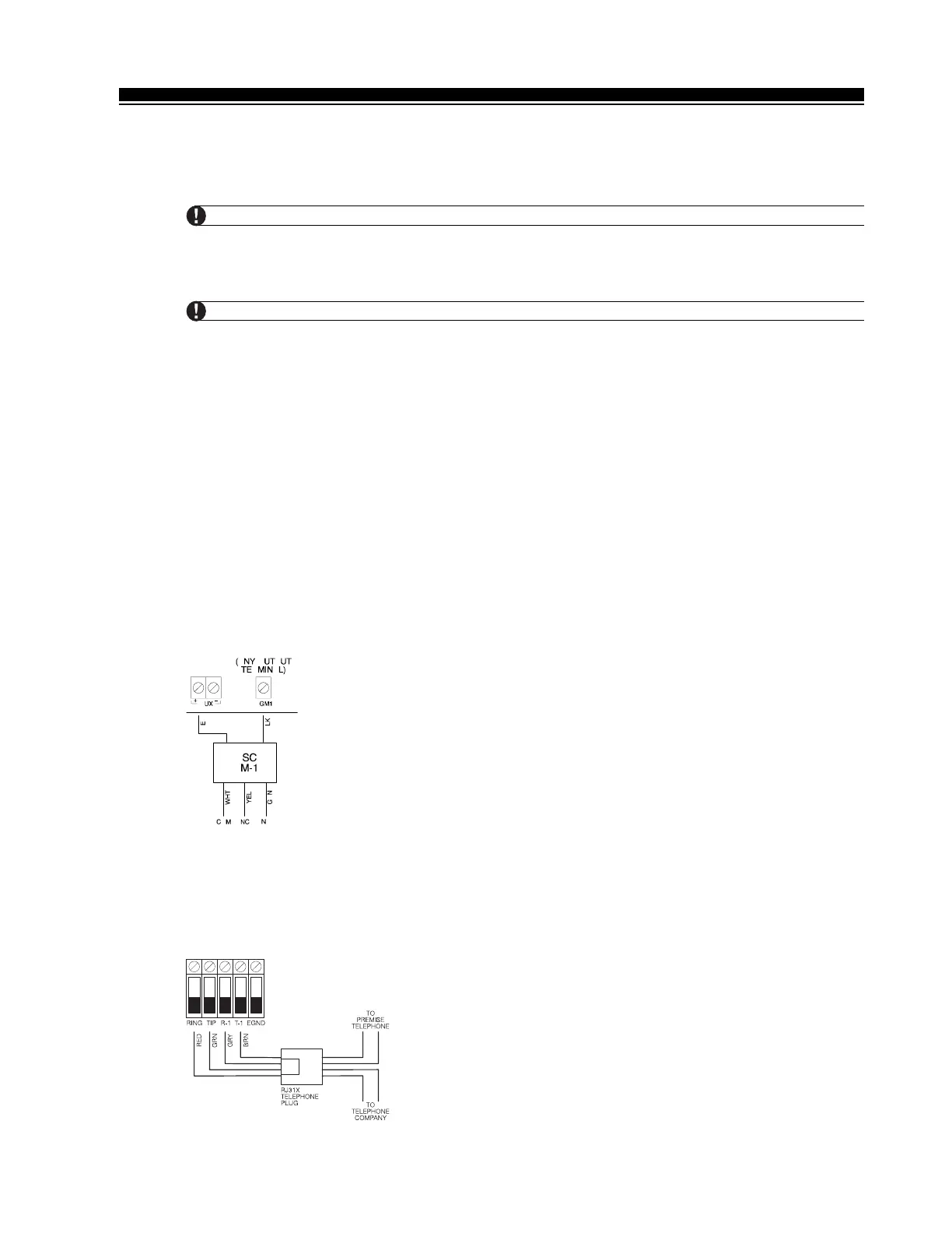
Telephone Connection Terminals - TIP, RING, T-1, R-1
If a telephone line is required for central station communication or downloading, connect an RJ-31X jack
in the following manner:
• RING - Red Wire _______ Incoming line from
• TIP - Green Wire telephone company
• R-1 - Grey Wire ________ Outgoing line to
• T-1 - Brown Wire house telephone(s)