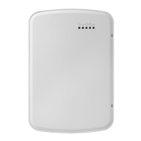
Enroll Alarm.com Image Sensor
Note: This feature can be enabled or disabled on the product. Check with your installer if this feature is activ-
ated in your application.
Alarm.com's Image Sensor built-in capability is not UL evaluated.
1. Ensure batteries are removed from the sensor.
2. On the panel, enter the Interactive Services menu. Interactive Services can be accessed, using section
[851] of Installer Programming.
3. Press [*][8] [Installer Code] [851].
4. Scroll to Image Sensor Setup and press [*].
5. Scroll to Learn Image Sensor and press [*]. The keypad displays “Power up or reset I.S. now.”
6. Insert the batteries into the sensor. Wait approximately 20 seconds for the control panel screen to display:
“I.S. [x] Added as Sensor [y].” The LED on the sensor turns solid for 5 seconds once the sensor has
enrolled.
7. Perform another panel comm-test to ensure that Alarm.com receives the updated device equipment list.
This speeds up the sensor initialization process.
l The zone is configured as a virtual zone and programmed automatically into the next available slot in
section [560][001]-[032] starting at zone 126 and counting down for each additional Image Sensor added.
l Once enrolled, the Image Sensor will appear as a normal zone.
l By default, the Image Sensor is enrolled as an Interior Stay/Away zone in zone type 005. Zone type and
attributes can be assigned in the installer menu, in a similar way as regular zones. For more information,
refer to the "Zone Setup" section of the PowerSeries Neo Alarm Controller Reference Manual.
Panel settings
Central station and telephone line settings
Central station and telephone line settings are automatically configured through the CS Forwarding Settings
page of the Alarm.com Dealer Site. The following are the panel settings that are configured through the
Dealer Site page (when required) and must not be configured in the panel:
Section Option Description
015 7 Telephone line monitoring
300 [001] -- Panel Communication Path - Receiver 1
300 [002] -- Panel Communication Path - Receiver 2
300 [003] -- Panel Communication Path - Receiver 3
300 [004] -- Panel Communication Path - Receiver 4
301 [001] -- Communication telephone number 1
301 [002] -- Communication telephone number 2
301 [003] -- Communication telephone number 3
301 [004] -- Communication telephone number 4
309 [001] -- System Call Direction - Maintenance
309 [002] -- System Call Direction - Test Transmission
310 [000] -- System account number
310 [001] -- Partition 1 account number
310 [002] -- Partition 2 account number
310 [003] -- Partition 3 account number
310 [004] -- Partition 4 account number
- 13 -
Installation

 Loading...