PowerSeries Neo Installation Guide
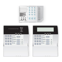
Figure 1-1 Corbus Wiring
Module (A) is wired correctly as it is within 1,000'/305m of the panel, in wire
distance. Module (B) is wired correctly as it is within 1,000'/305m of the panel,
in wire distance. Module (C) is NOT wired correctly as it is farther than
1,000'/305m from the panel.
Current Ratings
In order for the system to operate properly, the power output of the alarm
controller and power supply modules cannot be exceeded. Use the following data
to ensure that the available current is not exceeded.
Table 1-1 System Output Ratings
Device Output Rating (12VDC)
HS2016
HS2032
HS2064
HS2064 E
HS2128
HS2128 E
AUX: 700mA. Subtract the listed rating for each keypad, expansion
module and accessory connected to AUX or Corbus. At least
100mA must be reserved for the Corbus.
BELL: 700mA. Continuous rating. 2.0A. short term. Available only
with standby battery connected. Not for UL/ULC or EN cer-
tified applications.
HSM2208 AUX: 250mA. Continuous rating. Subtract for each device con-
nected. Subtract the total load on this terminal from the alarm
panel AUX/Corbus output.
HSM2108 AUX: 100mA. Subtract for each device connected. Subtract the total
load on this terminal from the panel AUX/Corbus output.
Alarm Control Panel
AUX - 700mA available for devices connected to the AUX and PGM terminals,
and modules connected to Corbus terminals. At least 100mA must be reserved for
the Corbus.
Alarm Controller Current Calculation
Panel Calculation
Maximum (Standby or Alarm)
AUX (700mA max. including PGMs 1-4)
Corbus (700mA max.)***
PCLink+ (Alt. Com.:125mA)
Total (must not exceed 700mA)
***See Corbus Current Calculation Chart.
For UL, ULC and Commercial Listed applications, the total standby and alarm
current cannot exceed 700mA.
Table 1-2 Corbus Current Calculation Chart
Item Current
(mA)
x Quantity Total
(mA)
HS2016/HS2032/HS2064/HS2064
E/HS2128/HS2128 E
85 x 1 85
HS2LCD 105 x
HS2ICN 105 x
HS2LED 105 x
HS2LCDP 105 x
HS2ICNP 105 x
HS2LCDRF 105 x
HS2ICNRF 105 x
HS2ICNRFP 105 x
HS2TCHP 160 x
Current required for connected devices =
HSM2108* 30 x
AUXoutput current of HSM2108
HSM2208* 40 x
AUXoutput current of HSM2208
HSM2300/2204* 35 x
HSM2HOSTx 35 x
HSM2955** x
3G2080(R)E/TL2803G(R)E/TL280(R)E 125
(PCLINK)
x
Total Corbus Current =
*These units draw current from the Corbus to power devices external to the
module. This current must be added to the total Corbus current. See
manufacturer's specifications for the current draw of each device.
** For HSM2955 current draw refer to HSM2955 installation manual.
Capacitance Limits
An increase in capacitance on the Corbus affects data transmission and causes
the system to slow down. Capacitance increases for every foot of wire added to
the Corbus. The capacitance rating of the wire used will determine the maximum
length of the Corbus.
Table 1-3 Wire Capacitance
Wire Capacitance per 1000’
(300m)
Total Corbus Wire Length
15nF 5300’/1616m
20nF 4000’/1220m
25nF 3200’/976m
30nF 2666’/810m
35nF 2280’/693m
40nF 2000’/608m
AC (UL Listed Installations)
Transformer: DSC PTD1640U, PTD1640, PTC1640UG, PTC1640CG
Primary: 120V, 60Hz Class II
Secondary: 16.5VAC, 40VA Max.
Note: Use DSC PTC1640CG for Canadian installations.
Warning: Do not connect the battery or transformer until all other
wiring is complete.
For ULC S559 applications, Standex transformer (Model FTC3716) shall be
employed for direct-wiring.
Note: For UL/ULC installations use only 60Hz.
Batteries
Do not connect the battery until all other wiring is complete.
- 3 -
 Loading...