Do you have a question about the DSE 720 and is the answer not in the manual?
Highlights essential elements of a procedure for correctness.
Indicates procedure risking damage or destruction of equipment if not observed.
Indicates procedure risking injury or loss of life if not followed correctly.
Describes the process of manual start and operation of the generator.
Details how to perform test operations on the generator module.
Explains the automatic start and stop sequences based on mains status.
How the module indicates alarms through relevant LEDs.
Alerts for impending faults, allowing the engine to continue running.
Describes latching shutdowns that stop the generator and required resets.
Steps to enter the configuration mode when the module is stopped.
Process for modifying module parameters using the front panel interface.
Specifies the required dimensions for cutting the panel for mounting.
Information on the module's integrated cable management features.
Details operating temperature range and environmental requirements.
Provides physical dimensions and layout of the module's rear panel.
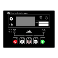
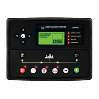
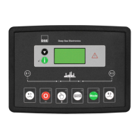
Illustrates the layout and components of the module's front panel.
Pin assignments and notes for the primary module connector.
Pin assignments and notes for the second module connector.
Pin assignments and notes for the third module connector.
Information on how to obtain replacement connector parts.
Essential checks and procedures before the system is first started.
| Manufacturer | Deep Sea Electronics |
|---|---|
| Category | Controller |
| Model | DSE 720 |
| Type | Generator Controller |
| Operating Temperature | -30°C to +70°C |
| Weight | 0.8 kg |
| DC Supply | 8 V to 35 V continuous |
| Display | LCD |
| Communication | RS232, RS485 |
| Protection Class | IP65 (front panel) |