- 16 - 057-001 720 Operating Instructions Issue 3.1 20/12/2005 AM
5 INSTALLATION INSTRUCTIONS
The model DSE 720 Module has been designed for front panel mounting. Fixing is by 4 x 4mm
screws into the panel fascia.
5.1 PANEL CUTOUT
182mm x 137mm (7.17” x 5.39”)
Maximum panel thickness – 8mm (0.3”)
In conditions of excessive vibration the module should be mounted on suitable anti-vibration
mountings.
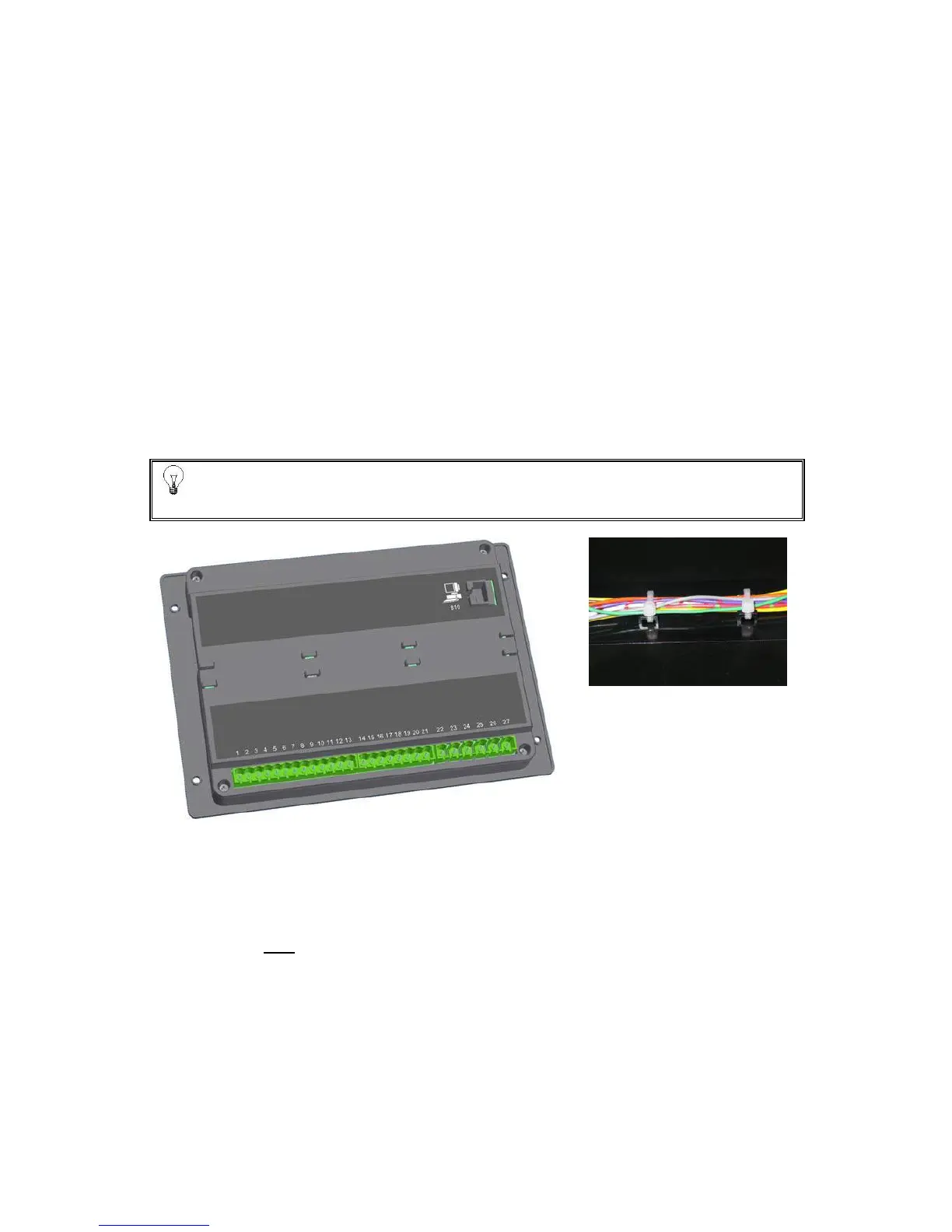
5.2 CABLE GUIDES
The model 720 has integral cable clamp/guides fitted to the rear of the module.
These enable the panel wiring to be tethered to the clamps helping to guide the cables neatly
around the panel. The clamps are designed for cable tie attachments and are spaced to match the
sticky backed cable tie bases commonly used in this type of application.
HINT!:- The cables can be placed in three different positions, above the clamps,
between the clamps and below the clamps.
Showing rear view of module without cables
Showing cable between the
clamps
5.3 COOLING
The module has been designed to operate over a wide temperature range -30ºC to +70ºC.
Allowances should be made for the temperature rise within the control panel enclosure. Care
should be taken NOT to mount possible heat sources near the module unless adequate ventilation
is provided. The relative humidity inside the control panel enclosure should not exceed 93%.