- 30 -
3.0 OPERATION
3.5.2 OIL TYPE
If the oil becomes discolored indicating
contamination, the contamination can be
take care of by installing a new filter-drier
in the liquid line and changing the oil.
WARNING:
Use Only Dunham-Bush Approved
Refrigeration Oil, Warranty Will Be
Void If Other Than Approved Oil Is
Used. It is recommended to change oil
annually to prolong the compressor
life-time.
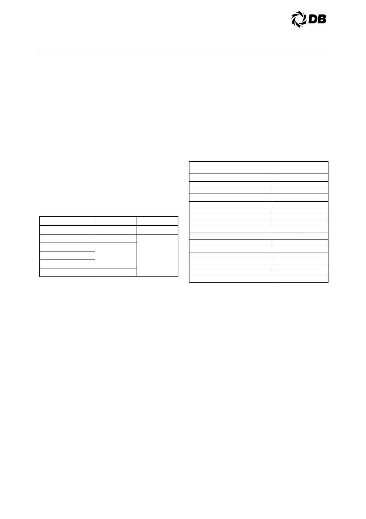
Oil charge for a complete recharge shown
in the following table. Oil type and
approved oils are also listed for each
compressor. After recharge the oil level
should be maintained per section 3.5.2.
COMPRESSOR MODEL OIL CHARGE (L) APPROVED OIL
HLH 068
1.6 PVE
SH 140
3.3
POE
(160SZ)
SH 180
6.7
SH 240
SH 300
SH 380
7.2
3.6 SYSTEM FLOW RATE
The quantity of chilled water being circulated can
be estimated by determining the water pressure
drop through the evaporator by reading GPM
[L/S] from the appropriate pressure drop curve.
(See Figure 3.6)
An alternate method of determining GPM [L/S]is
to measure pressure difference from pump inlet to
outlet and read GPM [L/S] from pump curve.
Water flow rate must not vary more than ±10%
from design flow rate.
3.7 SYSTEM CONTROL
3.7.1 CAPACITY CONTROL
The standard system capacity control
operates as follows:
- As the chiller load initially drops, the
suction of the compressor(s) starts
dropping proportionately, thus
balancing minor load variations.
- Variation of unit capacity in response to
system load requirements is controlled
by an operating thermostat, which
monitors the return water temperature.
- On multiple compressor units, capacity
is controlled by compressor staging.
Refer to Table 3.7.1 to determine the
capacity control scheme for your
specific unit.
TABLE 3.7.1 CAPACITY CONTROL
COMPRESSOR CYLINDER UNLOADING
AND STAGING SCHEDULE
ACDS CAPACITY
ACDS 010, 020, 030
COMPRESSOR OFF 0.0%
COMPRESSOR 1 ON 100% 50.0%
ACDS 040, 050, 060, 070, 080, 090, 100, 120
COMPRESSOR OFF 0.0%
COMPRESSOR 1 ON 100% 25.0%
COMPRESSOR 2 ON 100% 50.0%
COMPRESSOR 3 ON 100% 75.0%
COMPRESSOR 4 ON 100% 100.0%
ACDS 135, 150, 165, 180
COMPRESSOR OFF 0.0%
COMPRESSOR 1 ON 100% 16.7%
COMPRESSOR 2 ON 100% 33.3%
COMPRESSOR 3 ON 100% 50.0%
COMPRESSOR 4 ON 100% 66.7%
COMPRESSOR 5 ON 100% 83.4%
COMPRESSOR 6 ON 100% 100.0%
3.7.2
SOLID-STATE OPERATING
THERMOSTAT
3.7.2.1 General
A four-stage solid-state operating
thermostat, FSE, is used on all AC
packages. The opstat senses return
chilled water or air temperature and by
staging and/or unloading compressors is
able to control leaving chilled water or air
temperature to a narrow band of
temperature.
3.7.2.2 Opstat Settings
Each four-stage electronic opstat is
factory, adjusted to your specified
conditions, A field check of the controller
may be made by first determining your
design range (R). To determine the
range of a water chiller, subtract the
design leaving water temperature (TLW)
from the return water temperature
(TRW) (R =TRW-TLW).