- 44 -
Load/Unload Control
Manual Pulse Settings
Pulse Rate= 001sec
Pulse Width= 001sec
Technician Setpoints
Main Menu
Comp FLA Calibration
Sensor Calibration
Manual Control
Compressor Control
Sensors Override
Sensors Manual
Override
Supply Water Temp
Man Reading = 45.0°F [7.2°C]
Manual Override = NO
4.0 ELECTRICAL
NOTE: All compressors will revert back
to automatic control if the computer is
the computer is not given a load,
unload, or hold command at least once
every 15 minutes. A command can be
repeated to meet the 15 minute
requirement for manual control.
To the change the settings of
compressor load/Unload, follow the
above steps and go to compressor
control. Use down arrow key to move
the following and press to change the
settings.
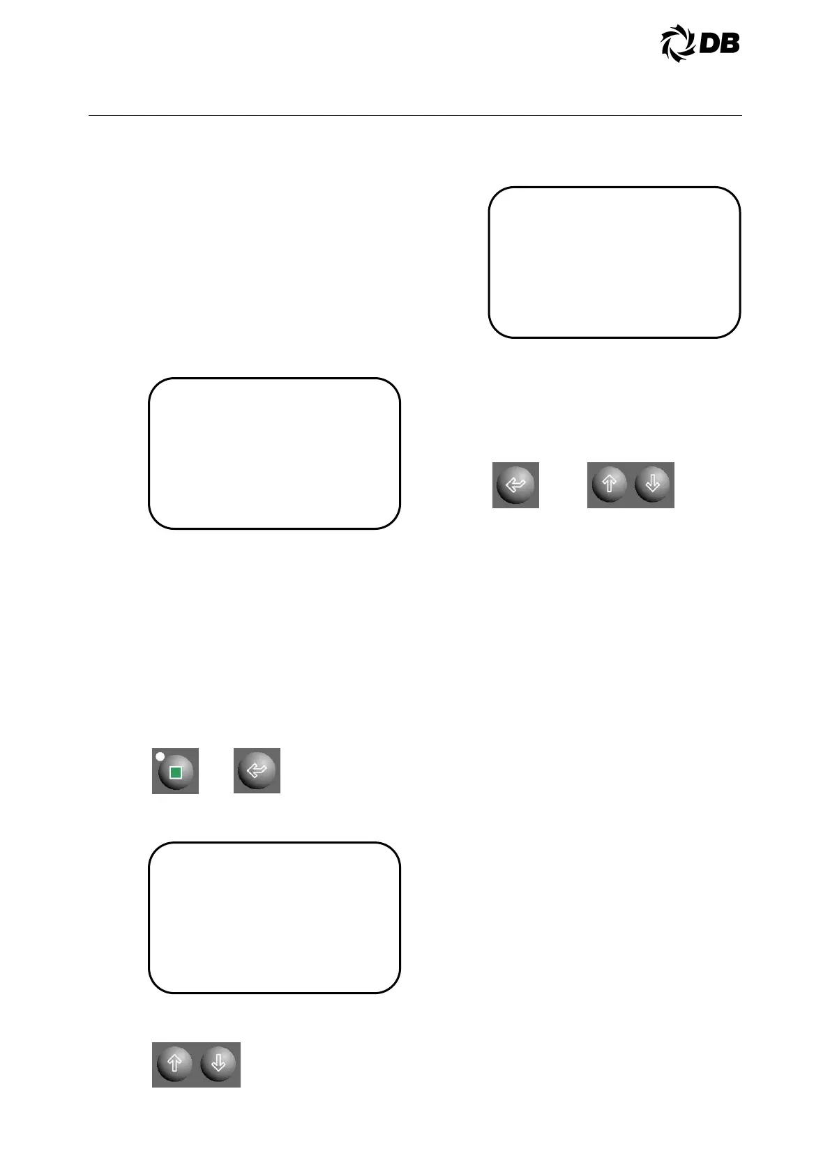
4.3.5.7 Sensors Override
Value of analog readings can be
temporary override during sensor
failure.
To override the analog readings, the
operator must be authorized at
technician level or higher.
Press technician key to go to technician
setpoints main menu and press enter
key five times to move the cursor to the
‘Sensors Override’ sub-menu:
The display is showing the data as
follows:
Use up or down arrow key to move the
cursor to the desired analog reading,
The display is showing the data as
follows:
Press enter key to move the cursor to
the “Man Reading” and use the up or
down arrow key to change the value of
the analog reading, press enter key
move the cursor to the “Manual
Override” to enable, or disable the
manual override control.
Repeat the above steps for other
sensors override.
Caution: Sensors override require continuous
monitoring and observation by the field service
personnel at all time during the unit operation.
Faulty sensor shall be replaced as soon as
possible in order to allow the unit to be running in
automatic mode.
4.3.6 CONTROL FUNCTIONS
4.3.6.1 Chilled Water Pump Interlock
And Flow Switch (CWP And
CWFS)
These are field installed switches, both
of which are used to ensure chilled
water flow before the unit is allowed to
start. Failure of either one during
operation will cause the compressor to
shut down.
A water flow alarm will be generated
and ‘Rest Alarm’ must be pressed to
clear the alarm.
4.3.6.2 Customer Control Interlock
Control contacts from an external
controller can be used to enable or
disable operation of the unit. The wiring
diagram specifies the terminals to
which the contacts must be wired. To
enable the unit, the contacts must be
closed. To disable the unit, the contacts
must be opened.