- 34 -
4.0 ELECTRICAL
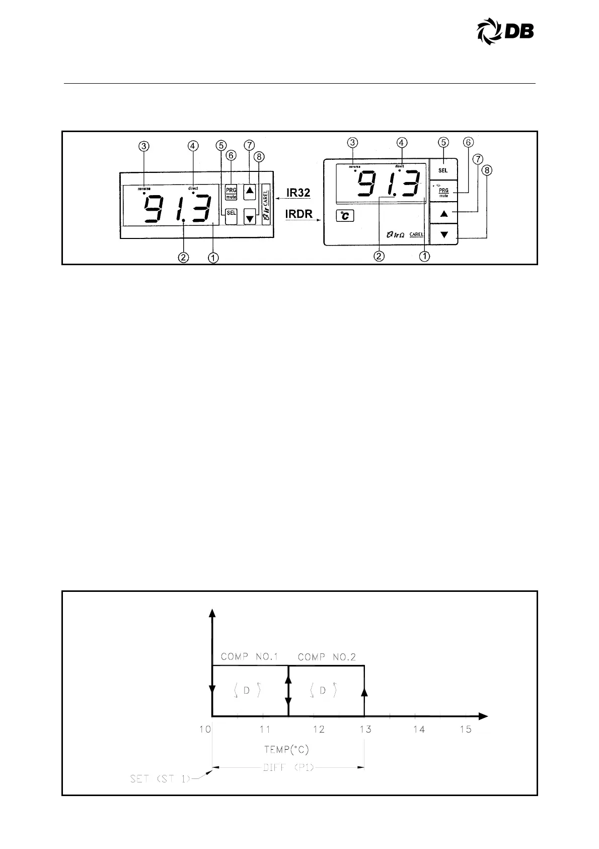
4.2 IR32 ELECTRONIC THERMOSTAT FRONT PANEL
1- Display: shows the value measured by the connected sensor. In the event of alarm condition the
sensor value will be displayed alternately with the codes of the active alarms. When programming the
instrument, the display shows the parameter codes being introduced and their values.
2- Decimal Point LED: lights up when the controlled parameter is displayed.
3- Reverse LED: flashes when at least one relay working in the "Reverse" mode is active. The Led
flashes as many times as the number of active 'reverse' relays. There is a two seconds' pause
between a flashing stage and the next one.
4- Direct LED: flashes when at least one relay working in the "Direct" mode is active. Its working logic is
the same as the "Reverse" LED.
5- SEL Button: displays and/or allows you to select the Set-point. If pressed for 5 seconds together with
PRG/MUTE it allows you to enter the password and the configuration parameters (having a "Cxx" type
code).
6- PRG/Mute Button: if pressed for 5 seconds it allows you to access the menu of the more frequently
used parameters (having a "Pxx" type code). In the event of alarm condition, it silences the buzzer
and, if pressed after the cause that determined the alarm has disappeared, it resets any other alarm. It
completes the programming procedure storing all the values of the modified parameters.
7- Button Δ: increases the value of the set-point or that of any other selected parametel:
8 - Button ∇ : decreases the value of the set-point or that of any other selected parametel: In NTC input
versions it can display the value of the second sensor (holding "Down" pressed while the display
shows the value of the main sensor).
Note: for Infrared Universal, Series models, please refer to the table at the end of the manual
4.2.1 TYPICAL CONTROL SEQUENCE WITH 2 STAGE OPERATING
THERMOSTAT AT 10°C RETURN WATER SETPOINT, 3.0°C DIFFERENTIAL