- 49 -
Graphic
Display
(option)
DB3 DB3 DB3
DB3
DB1
DB1
DB1
DB1 DB1
DB1 DB1
DB1
DBG1 DBG1 DBG1 DBG1
DBLAN
#1 #2 #3 #4 #5 #6
DB3
DB1
DB1
DBG1
DB3
DBG1
DB1
DB1
4.0 ELECTRICAL
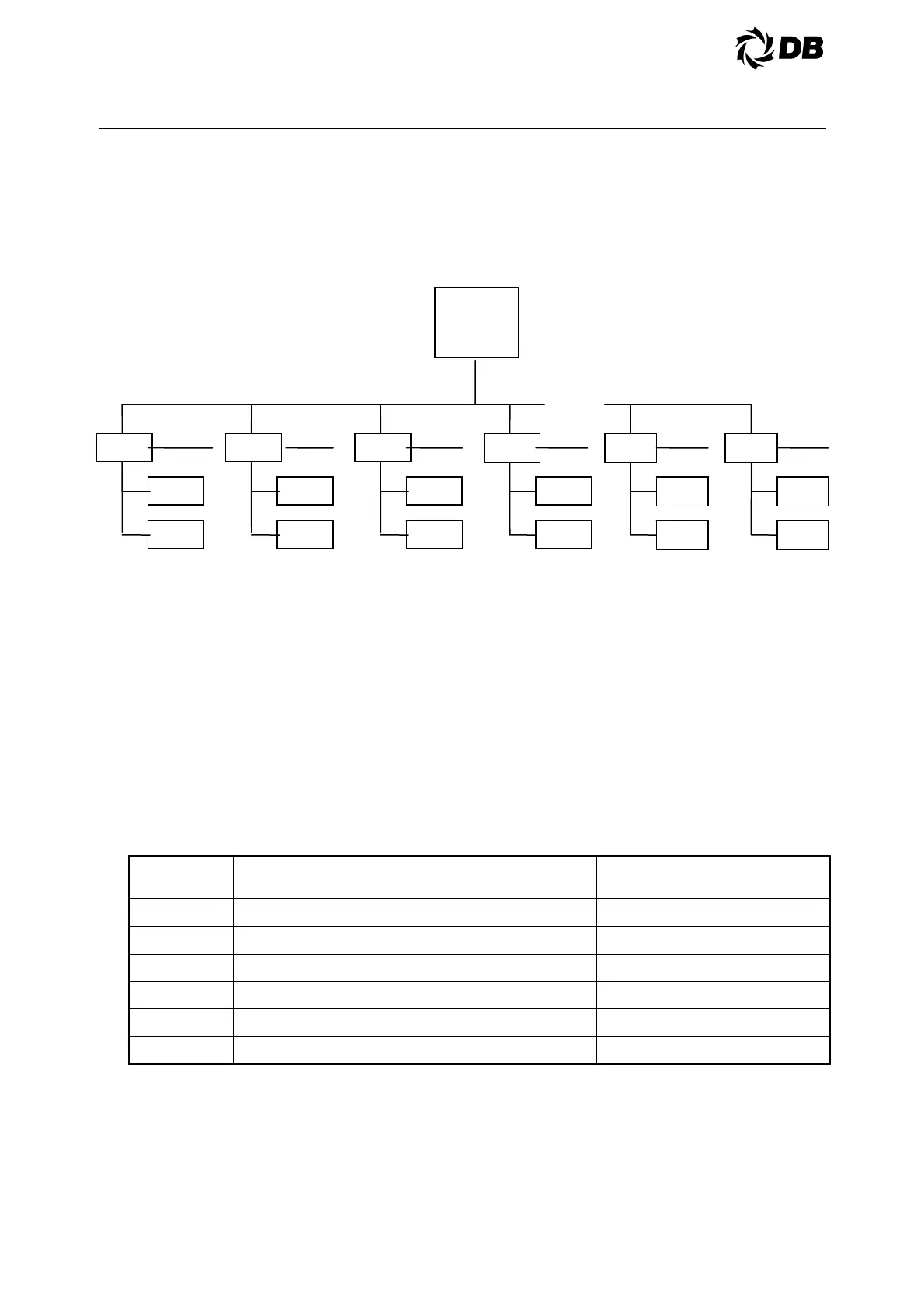
4.5.1 PRINCIPLE OF OPERATION VIA DBLAN COMMUNICATION BUS
Example: 6 chillers network with 4 units on duty and 2 units standby
Notes
a) Each chiller has a stand-alone master DB3 board and dedicated graphic display with multiple DB1
expanders board connected to J23 on DB3
b) Each chiller DB3 will be connected to DBLAN network through J11 connector
c) The chiller lead/lag selection can be determined by
D Manual lead/lag setpoint
D Schedule and holiday setup
D Alarm conditions
d) The lead/lag selection determine the chiller operation sequence as follows,
Lead chiller
selection
Normal chillers operation sequence When DBLAN fails
1 1, 2 & 3 on duty, 4, 5 & 6 standby 1, 2 & 3 on duty
2 2, 3 & 4 on duty, 5, 6 & 1 standby 2, 3 & 4 on duty
3 3, 4 & 5 on duty, 6, 1 & 2 standby 3, 4 & 5 on duty
4 4, 5 & 6 on duty, 1, 2 & 3 standby 4, 5 & 6 on duty
5 5, 6 & 1 on duty, 2, 3 & 4 standby 5, 6 & 1 on duty
6 6, 1 & 2 on duty, 3, 4 & 5 standby 6, 1 & 2 on duty
e) If the lead/lag selection is changed over to a different chiller, the sequence of operation will be
rotated
f) Each chiller will use a network address setpoint to determine individual chiller network address
g) Each chiller will require a dedicated chilled water pump or motorized valve digital output, unit enable
and chilled flow status digital inputs as well as enable next output command.