DSP 260
Owner‘s Manual 15
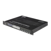
Un-balanced Input / Output Connections
Un-balanced connections can be made to the DSP 260, although induced noise from cabling may be
increased. Cables should also be less than 15” (5m) in length. Unbalanced connections can be 6dB lower
in level as well. To match the audio level obtained with a balanced connection, it is necessary to tie pin 3 to
ground at the XLR connector. This may increase noise.
RS-232
Two DSP 260s can be used in combination as a Master / Slave for managing larger
sound reinforcement systems. A 9-pin D-Sub connector is provided on the rear of
each unit for data line connections. A standard female-to-female RS-232 cable that
conforms to the null modem wiring convention is used to connect the two units. Cable
length should be kept to less than 45 feet (15 m) for the most reliable operation.
These cables are readily available at local computer dealers.
Operation of the DSP 260 9-pin port for RS-232 connections is selected in the Setup
menu.
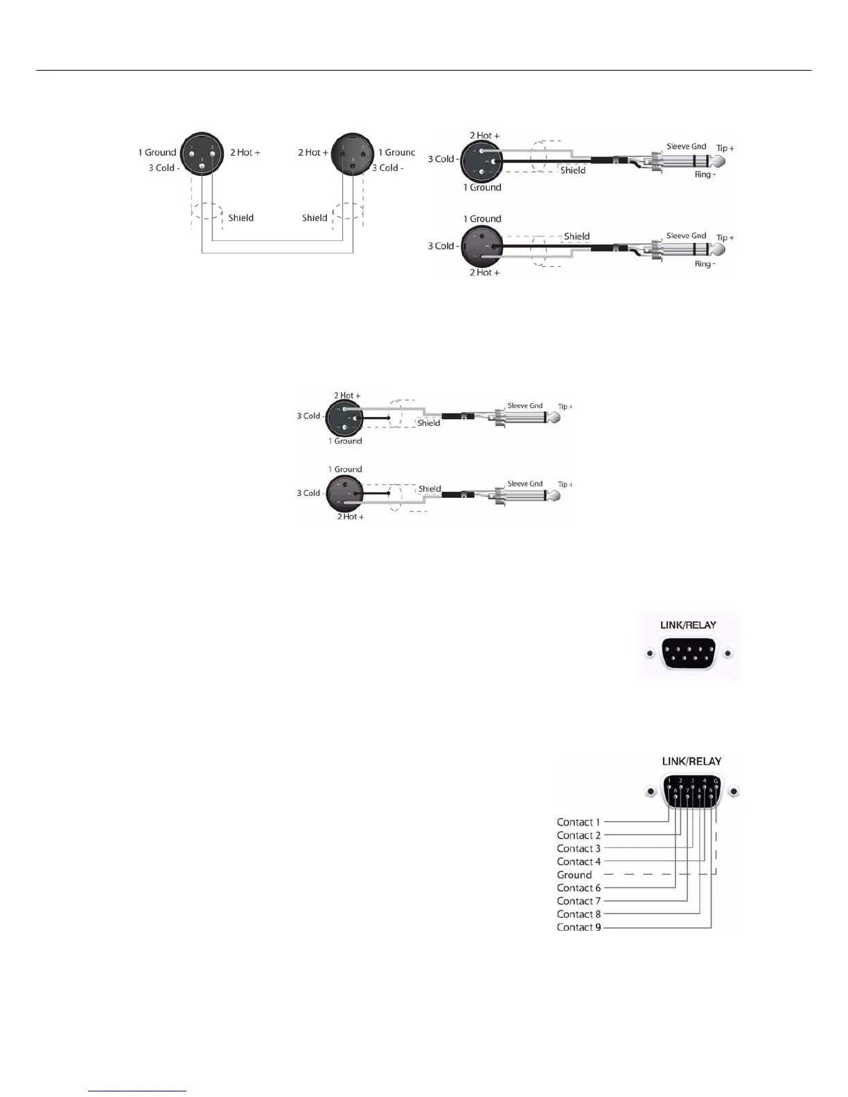
Relay Contact Closure
The same 9-pin port used for RS-232 connection to another DSP 260
can alternately be used to recall presets from relay contact closures.
Pins 1 – 4 and pins 5 – 9 are the input lines and pin 5 provides the
ground reference. When the DSP 260 detects a connection between
pin-5 ground and input pins, as completed by an external relay, a
preset assigned by the user to input pins is recalled into memory and
the DSP 260 returns to run-time mode.
 Loading...