DYNACORD
12
3 Controls & Connection
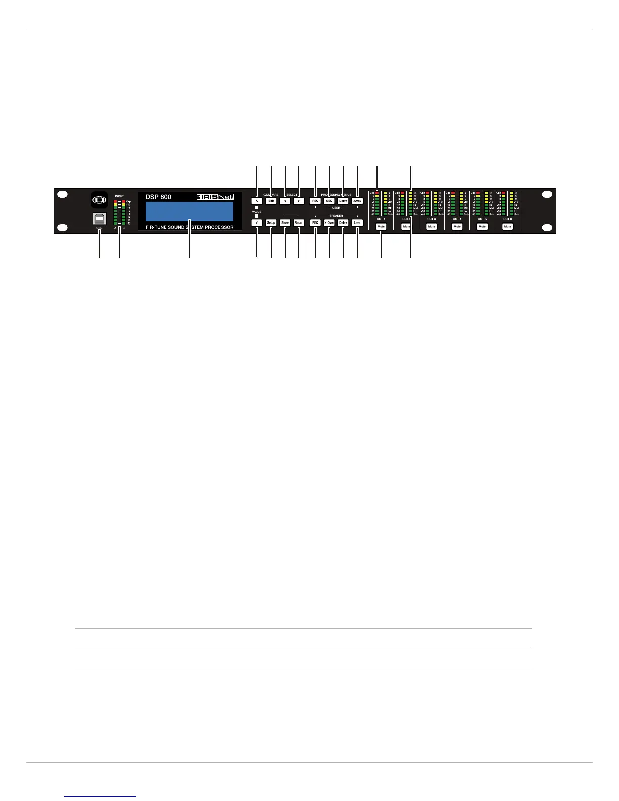
3.1 Front Panel
1 – USB CONNECTOR
USB 1.1 port for connection to a PC running Windows XP, Vista or 7. With a connected PC you may run the IRIS-Net
Application. The DSP 600 can be operated, edited and configured with an easy to use, intuitive interface. Any available
firmware updates downloadable from www.dynacord.com can be loaded via the USB port as well; allowing for easy up-
dates.
2 – INPUT
LEVEL METERS
The DSP 600 does not itself have input level controls. Proper input level adjustment is accomplished by setting the out-
put level from the (L / R) bus outputs from the connected mixer (or other audio output device), as the vast majority of
today’s mixer-outputs are dBu calibrated. When the mixer is operating at optimal levels, so is the DSP 600. The input
meters monitor the input level of either analog or AES-EBU inputs, depending on the input mode selection set in the
Setup Menu. Optimal signal-to-noise performance is obtained when the nominal (average), input level consistently lights
the +6dBu (green) and +12dBu (Yellow) LED indicators. As the DSP 600 is a digital audio device – and digital clipping
produces very unpleasant results, the Clip (red) LED should not light. If the DSP 600’s input does clip, reduce the output
level of the connected mixer. The -6dB PAD can be used for adjusting the input level also.
3 – LCD
DISPLAY
The back-lit, 192 x 32 graphic LCD display allows for operation and editing of the DSP 600 without the need for an at-
tached PC. The contrast can be set in the Setup Menu for varying lighting conditions and viewing angles. The LCD display
works in conjunction with Menu buttons, < SELECT > buttons and VALUE up/down buttons - to operate, navigate and
edit the DSP 600’s parameters. In Run mode, the LCD displays the number and name of the currently selected factory
or user preset. Pressing the Recall or Store buttons switches to their respective menus. Pressing the Edit or Setup menu
buttons switches the display to the last edited parameter.
In Edit and Setup mode, the top line of the LCD display shows the currently selected parameter edit screen. Use the <
SELECT > buttons to activate the top line of the display, and the VALUE up/down buttons to scroll through available
parameter edit screens.
4/5 – VALUE
UP/DOWN BUTTONS
Depending on the current LCD screen, the VALUE up/down buttons performs the following function:
6 – E
DIT / COMPARE BUTTONS
Pressing the Edit button while in Run mode places the current preset in Edit mode and the Edit button lights. The LCD
display shows the last edit screen that was selected. From this point, any edit screen can be displayed and altered.
Pressing the Edit button again “compares” the edited preset, if parameters have been altered, to the original un-edited
• Recall – Select forwards/backwards through the stored preset list to select a preset to be recalled to current memory.
• Store – Select User Preset destinations forwards/backwards to select a destination for the currently edited preset, scroll forwards through ANSI
character set to name preset.
• Edit / Setup – Scroll forwards/backwards through Edit / Setup screens when the top line of the LCD screen is active. Scroll forwards through values
for the selected parameter in an Edit / Setup screen.