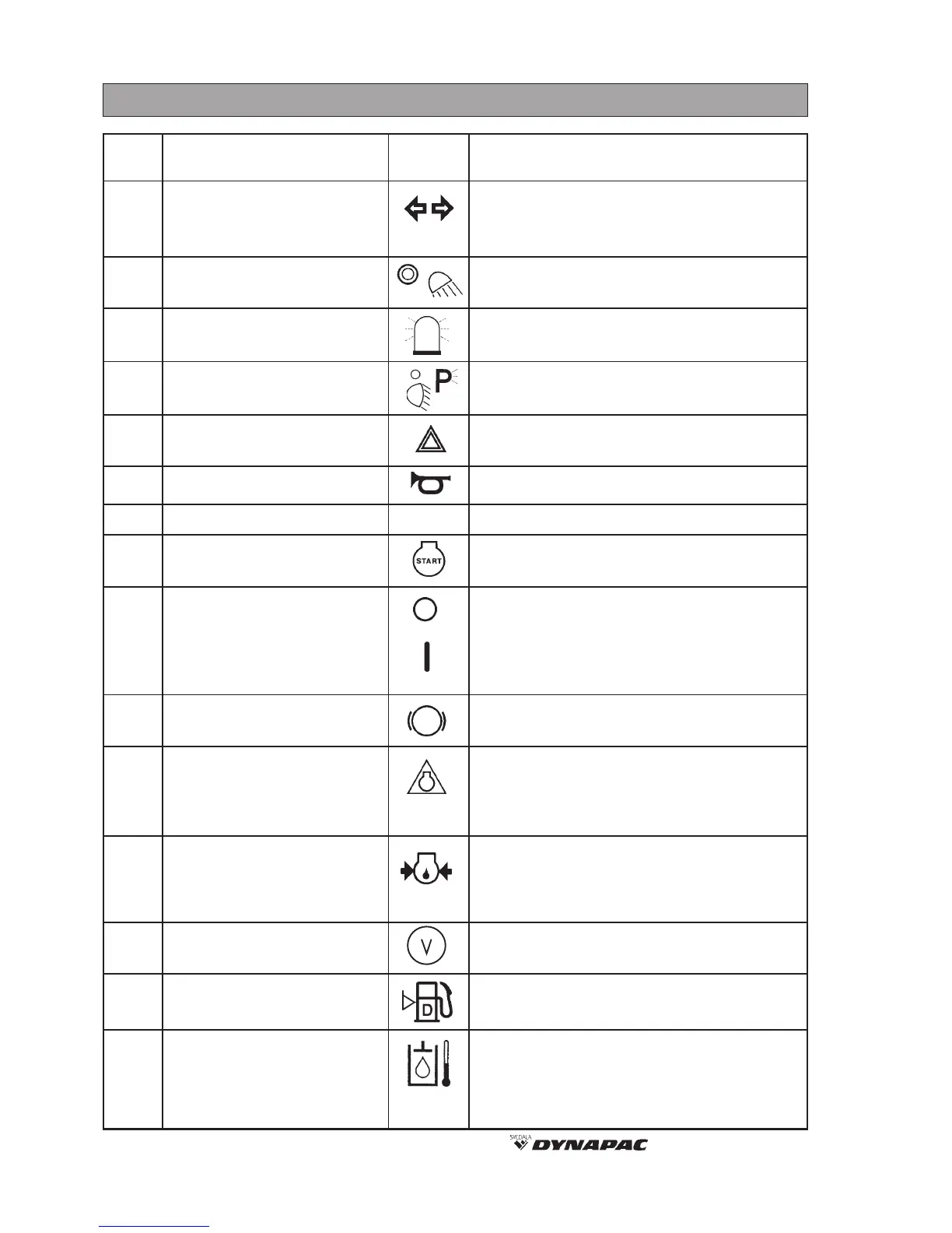
8 CA 251 O251-1EN1
INSTRUMENTS AND CONTROLS, FUNCTIONAL DESCRIPTION
STOP
Items Designation Symbol Function
in fig.4
Turn left to switch on the left direction
indicator, etc. The flashing indicator is OFF
in the middle position.
Turn right to switch on the working lights.
Turn right to switch on the hazard beacon.
Turn right to switch on the parking lights and
further right to switch on the dipped headlights.
Turn right to switch on the flashing warning
lights.
Press to sound the horn.
Press to run the starter motor.
In position O the electric circuit is broken.
In position I all electric instruments and
controls are powered.
The lamp lights while the brake is applied.
Lights while the parking brake is applied.
Press to activate the reserve brake. Press
when the machine is stationary to activate
the parking brake.
Pull out to release the brakes.
The warning lamp lights if lubricating oil
pressure is too low.
Stop the engine immediately and remedy the
cause.
Indicates voltage of the electrical system.
Normal indication is 12–15 Volt.
Indicates level of the fuel tank.
Indicates temperature of the hydraulic fluid.
Normal temperature range 65°C–80°C
(149°F–176°F). Stop the engine if the meter
indicates more than 85°C (185°F) and
remedy the cause.
1 Direction indicator
(optional equipment)
2 Working lights
(optional equipment)
3 Hazard beacon
(optional equipment)
4 Driving lights
(optional equipment)
5 Hazard flashers
(optional equipment)
6 Horn
7 - (optional equipment)
8 Starter contact
9 Switch
10 Brake warning lamp
11 Reserve brake/
Parking brake
(red knob)
12 Warning lamp, oil pressure
13 Voltmeter
14 Fuel gauge
15 Temperature gauge
hydraulic fluid